
Carel PZGXS0J111
Carel PZGXS0J111 റഫ്രിജറേഷൻ കൂളർ കൺട്രോൾ ടെമ്പറേച്ചർ കൺട്രോളർ യൂസർ മാനുവൽ
Model: PZGXS0J111 | Brand: Carel
1. ആമുഖം
This manual provides detailed instructions for the installation, operation, and maintenance of the Carel PZGXS0J111 Refrigeration Cooler Control Temperature Controller. This device is designed for precise temperature management in refrigeration systems, display cabinets, and showcases. Please read this manual thoroughly before installation and operation to ensure safe and efficient use.

ചിത്രം 1: മുൻഭാഗം view of the Carel PZGXS0J111 controller, showing the digital display and control buttons.
2 സുരക്ഷാ വിവരങ്ങൾ
Adherence to safety standards is crucial for the proper functioning and longevity of the device, as well as for user safety. This controller complies with relevant European standards.
- കണക്ഷൻ കേബിളുകൾ: Ensure connection cables guarantee insulation up to 90°C.
- 12 Vac Versions: For 12 Vac versions, use Class II transformers. To comply with immunity standards, the transformer must be a specified CAREL model. Double insulation cannot be guaranteed between power supply and relay outputs for 12 Vac/dc versions; use only safety low voltage loads (up to 42 V effective rated value).
- ഇൻസ്റ്റലേഷൻ ക്ലിയറൻസ്: Maintain a space of at least 10 mm between the case and nearby conductive parts.
- Digital and Analog Input Connections: For connections less than 30 m away, adopt suitable measures for separating cables to ensure compliance with immunity standards.
- Output Cable Security: Secure the connection cables of the outputs to avoid contact with very low voltagഇ ഭാഗങ്ങൾ.

Figure 2: Excerpt from the safety standards document, detailing insulation, transformer, and installation clearance requirements.
3 സാങ്കേതിക സവിശേഷതകൾ
The Carel PZGXS0J111 is a robust electronic microprocessor controller designed for various refrigeration applications. Below are its key technical specifications:
| ഫീച്ചർ | സ്പെസിഫിക്കേഷൻ |
|---|---|
| വൈദ്യുതി വിതരണം | 115 Vac +10/-15% 50/60 Hz |
| റേറ്റുചെയ്ത പവർ | 3 വി.എ |
| ഇൻപുട്ടുകൾ | NTC or PTC probes (1 or 3 inputs), Digital input as alternative to third probe |
| റിലേ p ട്ട്പുട്ടുകൾ | 2 HP relay: UL 12 A Res. 12 FLA 72 LRA - 240 Vac; 16 A relay: UL 8 A Res. 10 FLA 60 LRA - 240 Vac |
| അന്വേഷണത്തിന്റെ തരം | Std CAREL NTC 10 kΩ at 25°C, Std CAREL PTC 990 Ω at 25°C |
| കണക്ഷനുകൾ | Screw terminals for cables with cross-sect. from 0.5 mm² to 1.5 mm². Plug-in terminals for screw blocks or with crimped contact (cable cross-sect. up to 2.5 mm²). Rated maximum current per terminal 12 A. |
| അസംബ്ലി | Terminal: using screws from the front panel or with rear brackets. Interface: with mounting, 4 screws, spacing 101x151 mm. |
| പ്രദർശിപ്പിക്കുക | 3 digit LED display with sign (-999 to 999) and decimal point, six status LEDs |
| പ്രവർത്തന വ്യവസ്ഥകൾ | -10T50 °C - humidity <90% RH non-condensing |
| സംഭരണ വ്യവസ്ഥകൾ | -20T70 °C - humidity <90% RH non-condensing |
| അളവെടുപ്പ് പരിധി | -50T90 °C (-58T194 °F) - resolution 0.1 °C/°F |
| Front Panel Index of Protection | Panel installation with IP65 type 1 gasket |
| കേസ് | Plastic terminal, H76xL36xW65 mm |
| സർട്ടിഫിക്കേഷൻ | NSF, cURus, EAC CE |
| വാല്യംtage | 115 വോൾട്ട് |
| നിറം | കറുപ്പ് |
| യു.പി.സി | 661020725184 |
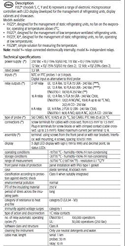
Figure 3: Detailed technical specifications, including power supply, inputs, outputs, and environmental conditions.
4. ഇൻസ്റ്റലേഷനും വയറിംഗും
Proper installation is critical for the controller's performance and safety. Refer to the wiring diagrams and ensure all connections are secure and comply with local electrical codes.
4.1 വയറിംഗ് ഡയഗ്രം
The controller features screw terminals for secure wiring. Ensure to use copper conductors only, as indicated on the device label.

ചിത്രം 4: പിൻഭാഗം view of the controller displaying the terminal block layout and electrical specifications. Note the "Use copper conductors only" instruction.

Figure 5: Close-up of the wiring terminals, indicating connections for power (115V~), probes (NTC, AMB.T, DEF.T), and digital inputs (DI/NTC).
4.2 ടെർമിനൽ കണക്ഷനുകൾ
- ടെർമിനലുകൾ 1-3: AUX and L (Line) connections.
- ടെർമിനലുകൾ 4-5: L (Line) and N (Neutral) for 115V~ power supply.
- ടെർമിനലുകൾ 6-7: AMB.T (Ambient Temperature) probe.
- ടെർമിനലുകൾ 8-9: NTC (Negative Temperature Coefficient) probes.
- ടെർമിനലുകൾ 10-11: DEF.T (Defrost Temperature) probe and DI/NTC (Digital Input/NTC) connections.
Ensure proper polarity and secure connections for all wires. The terminal blocks are designed for easy and reliable wiring.

ചിത്രം 6: വിശദമായി view of the green screw terminal blocks, highlighting the robust connection points.
4.3 മൗണ്ടിംഗ്
The controller is designed for panel installation. It uses 4 screws for mounting with a spacing of 101x151 mm. Ensure the panel opening is correctly sized for a snug fit and IP65 protection.

Figure 7: Yellow push clips, likely used for securing the controller during panel mounting or for cable management.
5. ഓപ്പറേഷൻ
The Carel PZGXS0J111 features an intuitive interface with a 3-digit LED display and several buttons for control and configuration.
5.1 Display and Functions
The display shows the value of the probe set using parameter P1. An ambient probe, defrost probe, and third probe are available. LEDs indicate the activation of control functions.
| LED ഐക്കൺ | ഫംഗ്ഷൻ | സാധാരണ പ്രവർത്തനം | മിന്നിമറയുക | സ്റ്റാർട്ടപ്പ് |
|---|---|---|---|---|
| ❄️ | കംപ്രസ്സർ | on | അഭ്യർത്ഥന | ON |
| 💨 | ഫാൻ | on | അഭ്യർത്ഥന | ON |
| 💧 | ഡിഫ്രോസ്റ്റ് | on | അഭ്യർത്ഥന | ON |
| ഓക്സ് | ഔട്ട്പുട്ട് ഓണാണ് | ഔട്ട്പുട്ട് ഓഫ് | - | ON |
| 🔔 | അലാറം | അലാറം ഇല്ല | - | ON |
| 🕒 | ക്ലോക്ക് | RTC fitted or disabled, at least 1 time band set | RTC not fitted or disabled, not even 1 time band set | RTC ഘടിപ്പിച്ചാൽ ഓൺ |
5.2 Button Functions (Models S, X, Y, C)
| ബട്ടൺ | സാധാരണ പ്രവർത്തനം | സ്റ്റാർട്ടപ്പ് |
|---|---|---|
| സെറ്റ് | Pressing the button alone: display set point. More than 3 s: display parameter setting menu. | Pressed together: Set point display. |
| യുപി (▲) | മൂല്യം വർദ്ധിപ്പിക്കുക. | - |
| ഡൗൺ (▼) | മൂല്യം കുറയ്ക്കുക. | - |
| ON/OFF (⏻) | More than 3 s: start/stop ON/OFF. | - |
| DEFROST (❄️💧) | More than 3 s: start defrost. | - |
| MUTE (🔔) | Mute alarm. | - |
5.3 Setting the Set Point (Desired Temperature)
- അമർത്തുക സെറ്റ് for 1 s; the set value will start flashing after a few moments.
- Increase or decrease the value using UP (▲) അല്ലെങ്കിൽ താഴേക്ക് (▼).
- അമർത്തുക സെറ്റ് പുതിയ മൂല്യം സ്ഥിരീകരിക്കാൻ.
5.4 Switching the Device ON/OFF
അമർത്തുക ON/OFF (⏻) for more than 3 s. The control and defrost algorithms are now disabled and the instrument displays the message "OFF" alternating with the temperature read by the set probe.
5.5 Manual Defrost (Models S, X, Y and C only)
അമർത്തുക DEFROST (❄️💧) for more than 3 s (the defrost starts only if the temperature conditions are valid).

Figure 8: Tables detailing LED indicators, button functions, and basic operation procedures.
6. പരിപാലനം
Regular maintenance ensures the optimal performance and longevity of your Carel PZGXS0J111 controller.
6.1 വൃത്തിയാക്കൽ
To clean the instrument, use only neutral detergents and water. Avoid abrasive cleaners or solvents that could damage the casinജി അല്ലെങ്കിൽ ഡിസ്പ്ലേ.
6.2 Probe and Cable Inspection
Periodically inspect probes and cables for any signs of wear, damage, or loose connections. Ensure probes are correctly positioned for accurate temperature readings. The maximum cable length for probes is 10 meters.
7. പ്രശ്നപരിഹാരം
This section provides guidance for common issues you might encounter with the Carel PZGXS0J111 controller. For complex problems, consult a qualified technician.
- Display shows "OFF": This indicates the device is switched off. Press and hold the ON/OFF button for more than 3 seconds to turn it back on.
- തെറ്റായ താപനില വായന: Check probe connections and ensure probes are not damaged or improperly installed. Verify the probe type setting in the controller's parameters.
- കൺട്രോളർ പ്രതികരിക്കുന്നില്ല: Check the power supply (115V AC). Ensure all wiring connections are secure. If the issue persists, a reset might be necessary (refer to advanced settings in the full manual, if available).
- അലാറം ഇൻഡിക്കേറ്റർ ഓണാണ്: Check the alarm conditions. Press the MUTE button to silence the alarm. Address the underlying cause of the alarm (e.g., temperature out of range).
8. വാറൻ്റി വിവരങ്ങൾ
For warranty details, please refer to the official Carel product warranty statement provided with your purchase or visit the Carel official website. Typically, warranty covers manufacturing defects under normal operating conditions.
- സംരക്ഷണ പദ്ധതികൾ: സ്റ്റാൻഡേർഡ് നിർമ്മാതാവിന്റെ വാറന്റിക്ക് പുറമേ വിപുലീകൃത കവറേജ് വാഗ്ദാനം ചെയ്യുന്ന അധിക സംരക്ഷണ പ്ലാനുകൾ വാങ്ങാൻ ലഭ്യമായേക്കാം. ഉദാ.ampഅവയിൽ 3 വർഷത്തെയും 4 വർഷത്തെയും സംരക്ഷണ പദ്ധതികൾ ഉൾപ്പെടുന്നു.
9. ഉപഭോക്തൃ പിന്തുണ
For technical assistance, spare parts, or further inquiries regarding your Carel PZGXS0J111 controller, please contact Carel customer support or your authorized distributor.
നിർമ്മാതാവ്: കരേൽ
Webസൈറ്റ്: www.carel.com (Please note: This is a generic link. Refer to your product packaging or official documentation for specific support contacts.)
Ask a question about this manual
Ask about setup, troubleshooting, compatibility, parts, safety, or missing instructions. Manuals+ will review the question and use this page’s manual context to help answer it.