
ആമുഖം
This manual provides detailed instructions for the installation, operation, and maintenance of the GEYA GRT8-A1 Delay On Single Function Time Relay. Please read thoroughly before use to ensure safe and correct operation.
ഉൽപ്പന്ന സവിശേഷതകൾ
- ഉയർന്ന പ്രകടനം: Delay can be set directly via the panel knob for convenient and intuitive adjustment.
- പ്രവർത്തന മോഡുകൾ: Features two optional modes: A (Delay ON) or B (Delay OFF).
- പ്രവർത്തന തത്വം: Function is controlled by supply voltage or time scale control input. Time scale ranges from 0.1s to 10 days, divided into 10 ranges (0.1-1s, 1-10s, 6-60s, 1-10min, 6-60min, 1-10hr, 0.1-1day, 1-10day, only ON, only OFF).
- വൈഡ് വോളിയംtagഇ പിന്തുണ: Compatible with AC/DC12-240V or AC230V.
- ഔട്ട്പുട്ട് കോൺടാക്റ്റ്: Available with 1SPDT (1NO1NC) or 2SPDT (2NO2NC) output contacts. Relay status is indicated by an LED.
- കോംപാക്റ്റ് ഡിസൈൻ: 1-MODULE, DIN rail mounting. Ultra-small size, only 18mm width, designed for 35mm rail mounting.
ഇൻസ്റ്റലേഷനും അളവുകളും
The GRT8-A1 relay is designed for easy installation on a standard DIN rail. Its compact dimensions ensure it fits efficiently into electrical panels.

ഫംഗ്ഷൻ മോഡുകൾ
The GRT8-A1 series offers two primary function modes: Delay ON (A) and Delay OFF (B), selectable via the front panel.
A - Delay ON
In Delay ON mode, the relay initiates a timed delay upon power-up. After the set delay period, the output contact closes, activating the connected load. The load remains active until power is removed.

B - Delay OFF
In Delay OFF mode, the connected load is immediately activated upon power-up. After the set delay period, the output contact opens, deactivating the load. This mode is suitable for applications where a device needs to run for a specific duration after being switched on.
വയറിംഗ് ഡയഗ്രം
Proper wiring is crucial for safe and correct operation. Refer to the diagrams below for connection details. Always ensure power is disconnected before performing any wiring.

Relay Wiring Example (Delay ON)
ഈ മുൻample demonstrates wiring for a Delay ON function to control a lamp using the GRT8-A1 AC230V model. Connect the Live (L) and Neutral (N) lines to the relay's power input (A1, A2). The trigger can be connected to the S terminal. The lamp is connected to the output contacts (15, 18) to receive power after the delay.

Wiring Demonstration Video
Video 1: This video demonstrates the wiring process for the GEYA GRT8-A1 time relay, showing how to connect power, load, and trigger for proper function. It also covers function demonstration and time setting.
സമയ ക്രമീകരണം
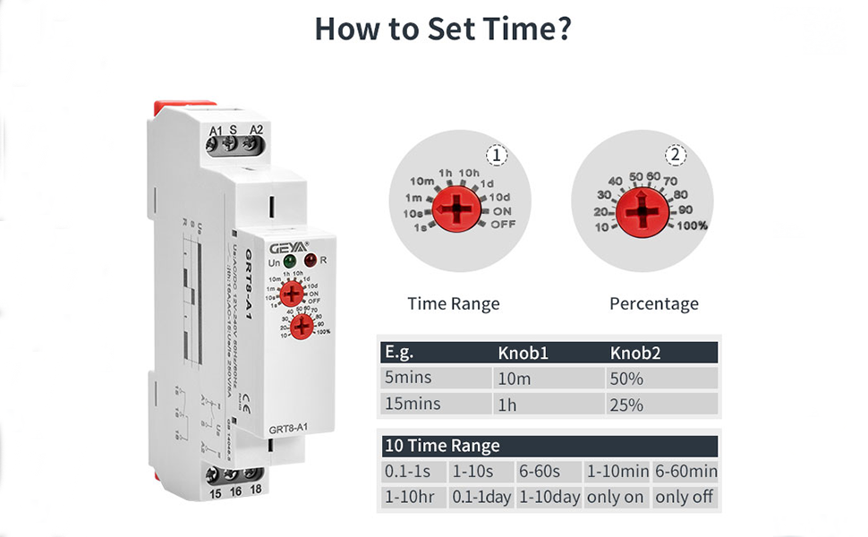
The delay time is set using two rotary knobs on the front panel of the relay. These knobs allow for precise adjustment of the delay period.

ക്രമീകരണ നടപടിക്രമം
- The upper knob (Knob 1) selects the time range. Options include 0.1-1s, 1-10s, 6-60s, 1-10min, 6-60min, 1-10hr, 0.1-1day, 1-10day, only ON, and only OFF.
- The lower knob (Knob 2) sets the percentage of the selected time range, adjustable from 10% to 100%.
ExampLe: To set a 5-second delay, first rotate the upper knob to the "10s" range. Then, adjust the lower knob to "50%". This calculates to 50% of 10 seconds, which is 5 seconds.
Time Setting Demonstration Video
Video 2: This video introduces how to use the GEYA GRT8-A1 time relay, including setting the delay time and demonstrating its operation with a load.
സാങ്കേതിക സവിശേഷതകൾ
Below are the detailed technical specifications for the GEYA GRT8-A1 Delay On Single Function Time Relay.

| സ്പെസിഫിക്കേഷൻ | മൂല്യം |
|---|---|
| ബന്ധപ്പെടാനുള്ള തരം | സാധാരണയായി തുറന്നിരിക്കുന്നു, സാധാരണയായി അടച്ചിരിക്കുന്നു |
| നിലവിലെ റേറ്റിംഗ് | 16 Amps |
| മൗണ്ടിംഗ് തരം | DIN റെയിൽ മ .ണ്ട് |
| ഓപ്പറേഷൻ മോഡ് | ഓട്ടോമാറ്റിക് |
| കോയിൽ വോളിയംtage | 12 വോൾട്ട് (DC) |
| നിലവിലെ റേറ്റിംഗുമായി ബന്ധപ്പെടുക | 16 Amps |
| പരമാവധി സ്വിച്ചിംഗ് കറന്റ് | 16 Amps |
| പരമാവധി സ്വിച്ചിംഗ് വോളിയംtage | 240 വോൾട്ട് |
| ടെർമിനലുകളുടെ എണ്ണം | 2 |
| സ്പെസിഫിക്കേഷൻ മെറ്റ് | ദിന് |
ട്രബിൾഷൂട്ടിംഗ്
- Relay not activating: Check power supply connections (A1, A2). Ensure the voltage is within the specified range (AC/DC12-240V or AC230V). Verify time settings are correctly configured and the delay period has elapsed.
- Load not switching: Inspect output contact wiring (15, 16, 18). Confirm the load is correctly connected to the appropriate normally open (NO) or normally closed (NC) terminals. Check the load's power requirements against the relay's maximum switching current (16 Ampഎസ്).
- തെറ്റായ കാലതാമസ സമയം: Re-verify the settings on both time range and percentage knobs. Ensure the screwdriver is properly seated when adjusting to avoid damage.
- LED സൂചകങ്ങൾ: Green LED (Un) indicates power supply. Red LED (R) indicates relay output status. If the green LED is off, check the power supply. If the red LED does not change state as expected, review wiring and time settings.
വാറൻ്റിയും പിന്തുണയും
For warranty information, technical assistance, or further inquiries, please contact GEYA customer support through their official channels or refer to the product packaging. Keep your purchase receipt for warranty claims.