
1. ആമുഖം
This instruction manual provides detailed information for the safe and efficient use of the HCDC DC12V 10Amp Forward and Reverse Relay Module (HD044 Series). This module is designed to control the direction of 2-wire DC motors and linear actuators, enabling forward and reverse motion for various applications. Please read this manual thoroughly before installation and operation to ensure proper functionality and to prevent damage to the device or connected equipment.

Figure 1: The HCDC HD044 Series Relay Module. This image shows the compact black module with its green 'REV' (Reverse) and red 'FWD' (Forward) push buttons, along with indicator LEDs and screw terminal block.
2 പ്രധാന സവിശേഷതകൾ
- Motor Reversing Capability: Powers any 2-wire reversing DC motor equipment.
- Integrated Control Buttons: Features built-in Forward (FWD) and Reverse (REV) momentary buttons for direct control.
- External Switch Support: Compatible with external momentary-action (self-resetting) or alternate-action (self-holding) switches.
- കോംപാക്റ്റ് ഡിസൈൻ: Housed in a compact plastic case with screw terminal blocks for easy mounting and connection.
- നില സൂചകങ്ങൾ: Includes a power indicator LED and separate LEDs for forward (red) and reverse (green) status.
- ഇലക്ട്രിക്കൽ റേറ്റിംഗുകൾ: Rated current of 10 Amps, operating voltag10V മുതൽ 15V DC വരെയുള്ള ഇ ശ്രേണി.
3. സജ്ജീകരണവും ഇൻസ്റ്റാളേഷനും
3.1 അൺപാക്കിംഗും പരിശോധനയും
Carefully remove the relay module from its packaging. Inspect the device for any visible damage that may have occurred during shipping. If any damage is found, do not proceed with installation and contact customer support.
3.2 മൗണ്ടിംഗ്
The module features mounting tabs for secure installation. Choose a dry, stable location away from excessive heat, moisture, and direct sunlight. Ensure adequate ventilation around the module.

Figure 2: Dimensions of the HCDC HD044 Series Relay Module. This image shows the physical dimensions of the module in millimeters, including length, width, and height, which are essential for proper mounting and integration into an enclosure.
3.3 പവർ ആവശ്യകതകൾ
The module operates on a DC voltage between 10V and 15V. Ensure your power supply meets these requirements and can provide sufficient current for both the module and the connected motor (up to 10 Ampഎസ്).
4. പ്രവർത്തന നിർദ്ദേശങ്ങൾ
4.1 Basic Operation (Using Onboard Buttons)
- Connect the module to a DC power source and a 2-wire DC motor as per the wiring diagrams in Section 5.
- ദി പവർ indicator LED will illuminate when power is supplied.
- അമർത്തുക FWD (Forward) button: The motor will move in one direction, and the red FWD status LED will light up. Release the button to stop the motor.
- അമർത്തുക റെവി (Reverse) button: The motor will move in the opposite direction, and the green റെവി status LED will light up. Release the button to stop the motor.
Note: The onboard buttons are momentary-action. The motor will only operate while the button is pressed.
4.2 Operation with External Switches
The module supports external momentary-action (self-resetting) or alternate-action (self-holding) switches. Refer to Section 5 for specific wiring configurations.
- Momentary-action (Self-resetting) Switch: When the external switch is pressed, the motor operates. When the switch is released, the motor stops.
- Alternate-action (Self-holding) Switch: Pressing the switch once will start the motor, and it will continue to run until the switch is pressed again to stop it.
5. വയറിംഗ് ഡയഗ്രമുകൾ
Proper wiring is crucial for the correct and safe operation of the relay module. Always ensure power is disconnected before making any wiring changes. The terminal block is clearly labeled for easy connection.
- M1, M2: Motor connections.
- V+, 0V: DC Power input (V+ for positive, 0V for negative).
- FWD, REV: External switch connections for Forward and Reverse control.
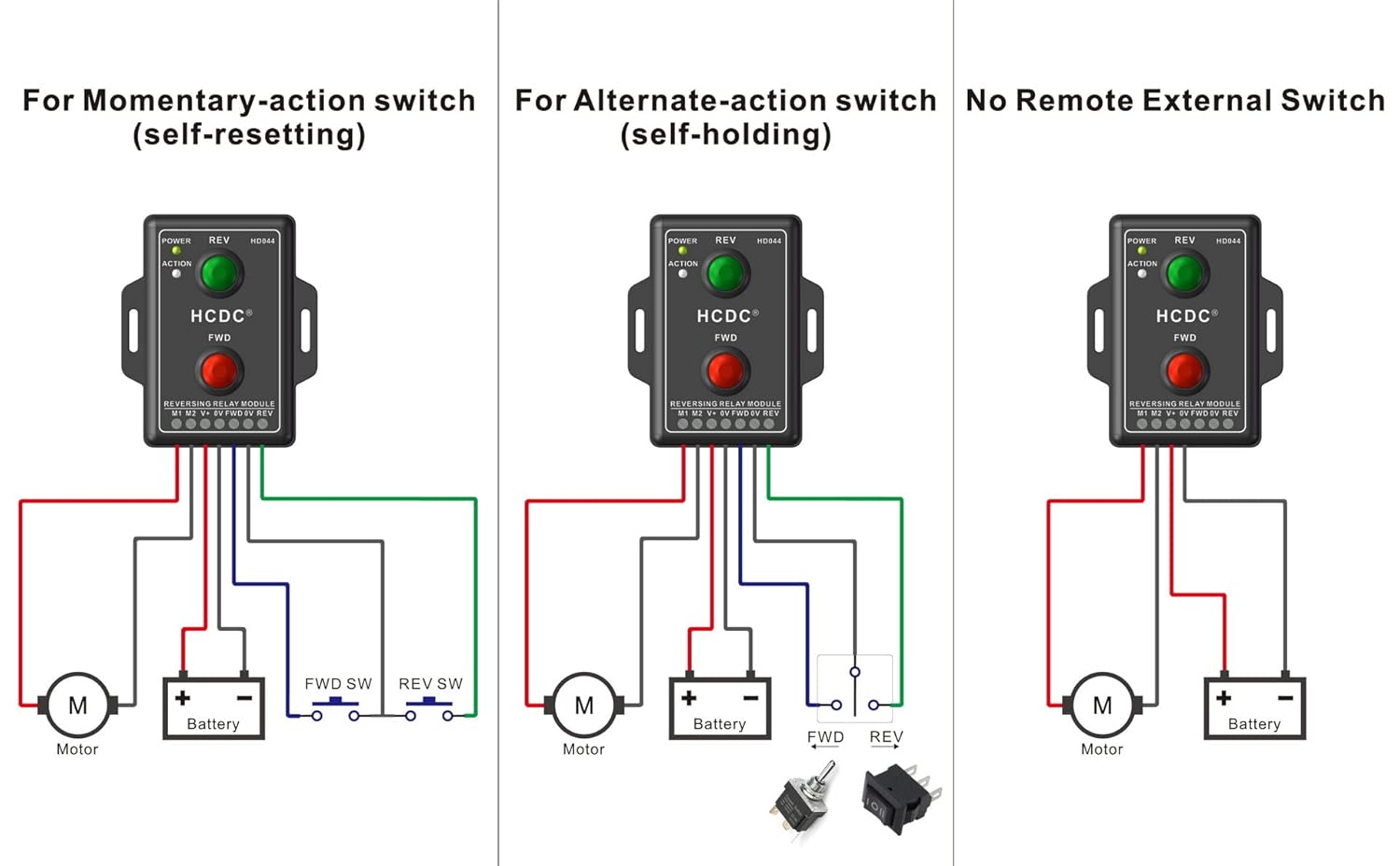
Figure 3: Comprehensive wiring diagrams for the HCDC HD044 Series Relay Module. This image illustrates three common wiring configurations: using a momentary-action switch, an alternate-action switch, and operating without any external switches, relying solely on the onboard buttons. Each diagram shows connections for the motor, battery, and external switches (if applicable).
5.1 Wiring for Momentary-Action External Switch (Self-Resetting)
Connect the external momentary switches between the FWD/REV terminals and the positive power supply (V+). When the FWD switch is pressed, the motor runs forward. When the REV switch is pressed, the motor runs in reverse. Releasing the switch stops the motor.
5.2 Wiring for Alternate-Action External Switch (Self-Holding)
Connect the external alternate-action switches between the FWD/REV terminals and the positive power supply (V+). Pressing the FWD switch once will start the motor in forward motion, and it will continue until the FWD switch is pressed again. The same applies to the REV switch for reverse motion.
5.3 Wiring without External Switch (Onboard Buttons Only)
If no external switches are desired, simply connect the motor to M1/M2 and the power supply to V+/0V. Control will be exclusively via the onboard FWD and REV buttons.
6 സാങ്കേതിക സവിശേഷതകൾ
| പരാമീറ്റർ | മൂല്യം |
|---|---|
| മോഡൽ നമ്പർ | HD044 സീരീസ് |
| ഓപ്പറേറ്റിംഗ് വോളിയംtage | 10വി - 15വി ഡിസി |
| റേറ്റുചെയ്ത കറൻ്റ് | 10 Amps |
| ബന്ധപ്പെടാനുള്ള തരം | സാധാരണയായി തുറന്നിരിക്കുന്നു |
| കണക്റ്റർ തരം | സ്ക്രൂ ടെർമിനൽ ബ്ലോക്ക് |
| മൗണ്ടിംഗ് തരം | ഉപരിതല മൗണ്ട് |
| അളവുകൾ (L x W x H) | Approx. 68.4 x 32.5 x 24.0 mm (Refer to Figure 2 for detailed dimensions) |
| ഭാരം | Approx. 472 g (Package weight) |
7. പ്രശ്നപരിഹാരം
If you encounter issues with your HCDC Relay Module, refer to the following troubleshooting guide:
| പ്രശ്നം | സാധ്യമായ കാരണം | പരിഹാരം |
|---|---|---|
| Module has no power (POWER LED off) | വൈദ്യുതി ഇല്ല, തെറ്റായ വോളിയംtage, or loose connections. | Check power supply (10-15V DC). Verify all power connections (V+, 0V) are secure. |
| മോട്ടോർ ചലിക്കുന്നില്ല | Incorrect motor wiring, motor fault, insufficient power, or button/switch issue. | Ensure motor is correctly connected to M1/M2. Check motor functionality independently. Verify power supply. Test onboard buttons. If using external switches, check their wiring and functionality. |
| Motor moves in wrong direction | Motor polarity reversed. | Reverse the motor connections at M1/M2 terminals. |
| External switch not working | Incorrect wiring for external switch, faulty switch. | Refer to Section 5 for correct external switch wiring. Test the external switch independently. |
| Module gets hot during operation | Overcurrent, motor drawing too much power. | Ensure motor current draw does not exceed 10 Amps. Check for motor stalls or excessive load. |
8. പരിപാലനം
The HCDC Relay Module is designed for reliable operation with minimal maintenance. Follow these guidelines to ensure longevity:
- വൃത്തിയാക്കൽ: മൊഡ്യൂൾ വൃത്തിയായും പൊടിയും അവശിഷ്ടങ്ങളും ഇല്ലാതെ സൂക്ഷിക്കുക. വൃത്തിയാക്കാൻ മൃദുവായതും ഉണങ്ങിയതുമായ തുണി ഉപയോഗിക്കുക. ലിക്വിഡ് ക്ലീനറുകളോ ലായകങ്ങളോ ഉപയോഗിക്കരുത്.
- പരിസ്ഥിതി വ്യവസ്ഥകൾ: Ensure the module is operated within its specified temperature and humidity ranges. Avoid exposure to corrosive gases or liquids.
- കണക്ഷൻ പരിശോധനകൾ: എല്ലാ വയറിംഗ് കണക്ഷനുകളും സുരക്ഷിതമാണെന്നും തുരുമ്പെടുക്കലിൽ നിന്ന് മുക്തമാണെന്നും ഉറപ്പാക്കാൻ ഇടയ്ക്കിടെ പരിശോധിക്കുക.
9. വാറൻ്റിയും പിന്തുണയും
വാറന്റി വിവരങ്ങൾക്കോ സാങ്കേതിക പിന്തുണയ്ക്കോ, ദയവായി റീട്ടെയിലറെയോ നിർമ്മാതാവിന്റെയോ ഉദ്യോഗസ്ഥനെയോ കാണുക. webഉൽപ്പന്നം വാങ്ങിയ സ്ഥലം. വാങ്ങിയതിന്റെ തെളിവായി നിങ്ങളുടെ വാങ്ങൽ രസീത് സൂക്ഷിക്കുക.
For further assistance, please contact HCDC customer support through their official channels.