
Flysky FS-iBH07 (Z49577)
Flysky FS-iBH07 7CH Expander User Manual
Model: FS-iBH07 (Z49577)
1. ഉൽപ്പന്നം കഴിഞ്ഞുview
The Flysky FS-iBH07 is a compact 7-channel expander designed for use with i-BUS2 protocol signal output functions. It provides additional PWM channels and allows for the connection of multiple i-BUS2 devices, making it suitable for various RC models including aircraft, cars, boats, and robots.
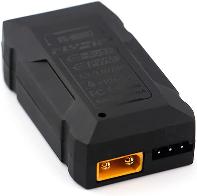
ചിത്രം 1: മുൻഭാഗം view of the Flysky FS-iBH07 7CH Expander. This image shows the compact black casing of the expander module, highlighting its primary form factor.
2 പ്രധാന സവിശേഷതകൾ
- Adaptive Transmitter: Compatible with products featuring i-BUS2 signal output function.
- Versatile Model Compatibility: Ideal for aircraft, cars, boats, and robots.
- 7 ചാനലുകൾ: Provides 7 output channels for expanded control.
- Flexible Data Output: Supports both PWM and i-BUS2 data output.
- ഒതുക്കമുള്ള വലിപ്പം: Dimensions of 46.5mm x 26.2mm x 12.6mm for easy integration.
- Channel Expansion: Meets requirements for PWM channel expansion or connecting multiple i-BUS2 devices.
3 സ്പെസിഫിക്കേഷനുകൾ
| പരാമീറ്റർ | മൂല്യം |
|---|---|
| ഉൽപ്പന്നത്തിൻ്റെ പേര് | FS-iBH07 |
| അഡാപ്റ്റീവ് ട്രാൻസ്മിറ്റർ | Products with i-BUS2 signal output function |
| മോഡൽ തരം | Aircraft, cars, boats, robots |
| ചാനലുകൾ | 7 |
| ഇൻപുട്ട് പവർ | 3.5 വി-9.0 വി (ഡിസി) |
| നിലവിലുള്ളത് | 15mA (5V) |
| ഡാറ്റ ഇൻപുട്ട് | i-BUS2 |
| ഡാറ്റ ഔട്ട്പുട്ട് | PWM/i-BUS2 |
| താപനില പരിധി | -10°C മുതൽ +60°C വരെ |
| ഈർപ്പം പരിധി | 20%~95% |
| വാട്ടർപ്രൂഫ് | പിപിഎക്സ് 6 |
| ഓൺലൈൻ അപ്ഡേറ്റ് | ഇല്ല |
| അളവുകൾ | 46.5mm x 26.2mm x 12.6mm |
| ഭാരം | 11.2 ഗ്രാം |
| സർട്ടിഫിക്കേഷൻ | CE, FCC |

Figure 2: Product packaging displaying detailed specifications and certifications. This image confirms the technical parameters and regulatory compliance of the FS-iBH07 expander.
4. പാക്കേജ് ഉള്ളടക്കം
പാക്കേജ് തുറക്കുമ്പോൾ, നിങ്ങൾ ഇനിപ്പറയുന്ന ഇനങ്ങൾ കണ്ടെത്തണം:
- 1x Flysky FS-iBH07 7CH Expander Module
- Connection Cables (as shown in Figure 3)
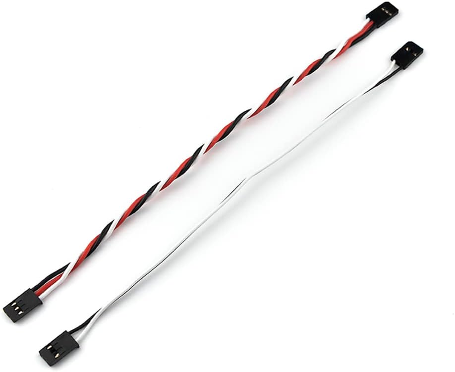
Figure 3: Included connection cables. These cables are essential for connecting the expander to your receiver and other components.
5. Product Diagram and Pinout
Understanding the layout and pin assignments of the FS-iBH07 is crucial for proper installation and operation. Refer to the diagrams below for detailed views of the expander's ports and indicators.

ചിത്രം 4: പൊട്ടിത്തെറിച്ചു view and pinout diagram of the FS-iBH07. This diagram labels various ports and features for easy identification.
Key to Diagram (Figure 4):
- Output 1 (PWM)
- Output 2 (PWM)
- Output 3 (PWM)
- Output 4 (PWM)
- Output 5 (PWM)
- Output 6 (PWM)
- Output 7 (PWM)
- i-BUS2 Input Port
- Power Input Port (3.5V-9.0V DC)
- മൗണ്ടിംഗ് ഹോൾ
- മൗണ്ടിംഗ് ഹോൾ
- മൗണ്ടിംഗ് ഹോൾ
- മൗണ്ടിംഗ് ഹോൾ
- LED സൂചകം

Figure 5: Close-up of the 7-channel PWM output ports. This image clearly shows the arrangement of the output pins labeled 1 through 7.
6. ഇൻസ്റ്റലേഷനും സജ്ജീകരണവും
Follow these steps to properly install and set up your FS-iBH07 expander:
- റിസീവറുമായി ബന്ധിപ്പിക്കുക: Connect the i-BUS2 input port (labeled [8] in Figure 4) of the FS-iBH07 to the i-BUS2 output port of your compatible Flysky receiver using the provided connection cable. Ensure the polarity is correct.
- പവർ കണക്ഷൻ: Connect a power source (3.5V-9.0V DC) to the power input port (labeled [9] in Figure 4). Ensure the voltagകേടുപാടുകൾ തടയുന്നതിന് e നിർദ്ദിഷ്ട പരിധിക്കുള്ളിലാണ്.
- PWM Device Connection: Connect your PWM-controlled devices (e.g., servos, ESCs) to the desired output channels (labeled [1] to [7] in Figure 4 and Figure 5). Each channel corresponds to a specific PWM output.
- സുരക്ഷിത മൗണ്ടിംഗ്: Use the mounting holes (labeled [10] to [13] in Figure 4) to securely mount the expander within your model. Ensure it is protected from vibrations and moisture.
- പ്രാരംഭ പവർ-അപ്പ്: Power on your receiver and transmitter. Observe the LED indicator (labeled [14] in Figure 4) on the FS-iBH07. A steady light typically indicates a successful connection and proper operation.
Note: Always refer to your receiver's manual for specific i-BUS2 output details and power supply recommendations.
7. ഓപ്പറേഷൻ
Once installed and powered, the FS-iBH07 expander operates by converting the i-BUS2 signal from your receiver into individual PWM signals for the 7 output channels. It also allows for the daisy-chaining of other i-BUS2 devices.
- PWM ഔട്ട്പുട്ട്: Each of the 7 output ports provides a standard PWM signal, allowing you to control servos, ESCs, or other PWM-compatible devices.
- i-BUS2 Passthrough: The expander acts as a hub for the i-BUS2 protocol, enabling the connection of multiple i-BUS2 devices in series.
- Signal Expansion: This module is particularly useful when your receiver has fewer PWM outputs than required for your model, or when you need to integrate multiple i-BUS2 sensors or modules.
8. പരിപാലനം
To ensure the longevity and reliable performance of your FS-iBH07 expander, follow these simple maintenance guidelines:
- വൃത്തിയായി സൂക്ഷിക്കു: Regularly clean the exterior of the expander with a soft, dry cloth. Avoid using solvents or harsh chemicals.
- ഈർപ്പത്തിൽ നിന്ന് സംരക്ഷിക്കുക: Although rated PPX6 water-resistant, avoid prolonged exposure to water or extreme humidity. Ensure connections are dry before powering on.
- കണക്ഷനുകൾ പരിശോധിക്കുക: Periodically inspect all wiring and connectors for signs of wear, corrosion, or loose connections. Secure any loose wires.
- സംഭരണം: When not in use, store the expander in a cool, dry place, away from direct sunlight and extreme temperatures.
- ശാരീരിക നാശം ഒഴിവാക്കുക: Protect the module from impacts or excessive force, which can damage internal components.
9. പ്രശ്നപരിഹാരം
If you encounter issues with your FS-iBH07 expander, consider the following common troubleshooting steps:
| പ്രശ്നം | സാധ്യമായ കാരണം | പരിഹാരം |
|---|---|---|
| No power/LED off | Incorrect power input voltage or polarity; loose power connection. | ഇൻപുട്ട് വോളിയം പരിശോധിക്കുകtage (3.5V-9.0V DC) and polarity. Check power cable connections. |
| No signal output from PWM channels | No i-BUS2 input signal; incorrect i-BUS2 connection; receiver not powered or bound. | Ensure i-BUS2 cable is securely connected and has correct polarity. Confirm receiver is powered and properly bound to the transmitter. Check receiver's i-BUS2 output. |
| Erratic behavior of connected devices | Interference; faulty connection; power supply issues. | Check for sources of electrical interference. Re-seat all connections. Ensure power supply is stable and sufficient for all connected devices. |
| Expander gets unusually hot | Overload; short circuit; faulty unit. | Disconnect all devices and power. Check for short circuits in wiring. Ensure total current draw does not exceed expander's capacity. If problem persists, discontinue use. |
If these steps do not resolve the issue, please contact your retailer or Flysky customer support for further assistance.
Ask a question about this manual
Ask about setup, troubleshooting, compatibility, parts, safety, or missing instructions. Manuals+ will review the question and use this page’s manual context to help answer it.