1. ആമുഖം
This manual provides detailed instructions for the installation, operation, and maintenance of your Flylin DC 6-60V 30A PWM DC Motor Speed Controller. This device is designed to precisely control the speed of DC brush motors within a voltage range of 6V to 60V, with a maximum current of 30A. It features a digital display for speed percentage, a momentary start/stop switch, and a speed control potentiometer for stepless adjustment.
2 സുരക്ഷാ വിവരങ്ങൾ
- ഇൻപുട്ട് വോളിയം ഉറപ്പാക്കുകtage is within the specified range of DC 6V-60V. Exceeding this range can damage the device.
- Always disconnect power before making any wiring connections or disconnections.
- Observe correct polarity for power input and motor connections. Incorrect wiring can lead to malfunction or damage.
- This controller is designed for DC brush motors. Do not use it with AC motors or other motor types.
- Avoid short circuits on the output terminals.
- Install the controller in a well-ventilated area to prevent overheating, especially during prolonged high-current operation.
- Keep the device away from moisture, dust, and corrosive substances.
3. ഉൽപ്പന്നം കഴിഞ്ഞുview
The Flylin DC Motor Speed Controller integrates a digital display, a speed adjustment potentiometer, and a start/stop switch for convenient motor speed management.


പ്രധാന ഘടകങ്ങൾ:
- Main Control Unit: Houses the circuit board and LED digital display.
- LED ഡിജിറ്റൽ ഡിസ്പ്ലേ: മോട്ടോർ വേഗത ഒരു ശതമാനമായി കാണിക്കുന്നുtagഇ (0-100%).
- Speed Control Potentiometer: Rotary knob for adjusting motor speed.
- ആരംഭിക്കുക/നിർത്തുക സ്വിച്ച്: Momentary push-button to start or stop the motor.
- സ്ക്രൂ ടെർമിനലുകൾ: For secure power input and motor output connections.


4 സ്പെസിഫിക്കേഷനുകൾ
Refer to the table below for detailed technical specifications of the Flylin DC Motor Speed Controller.
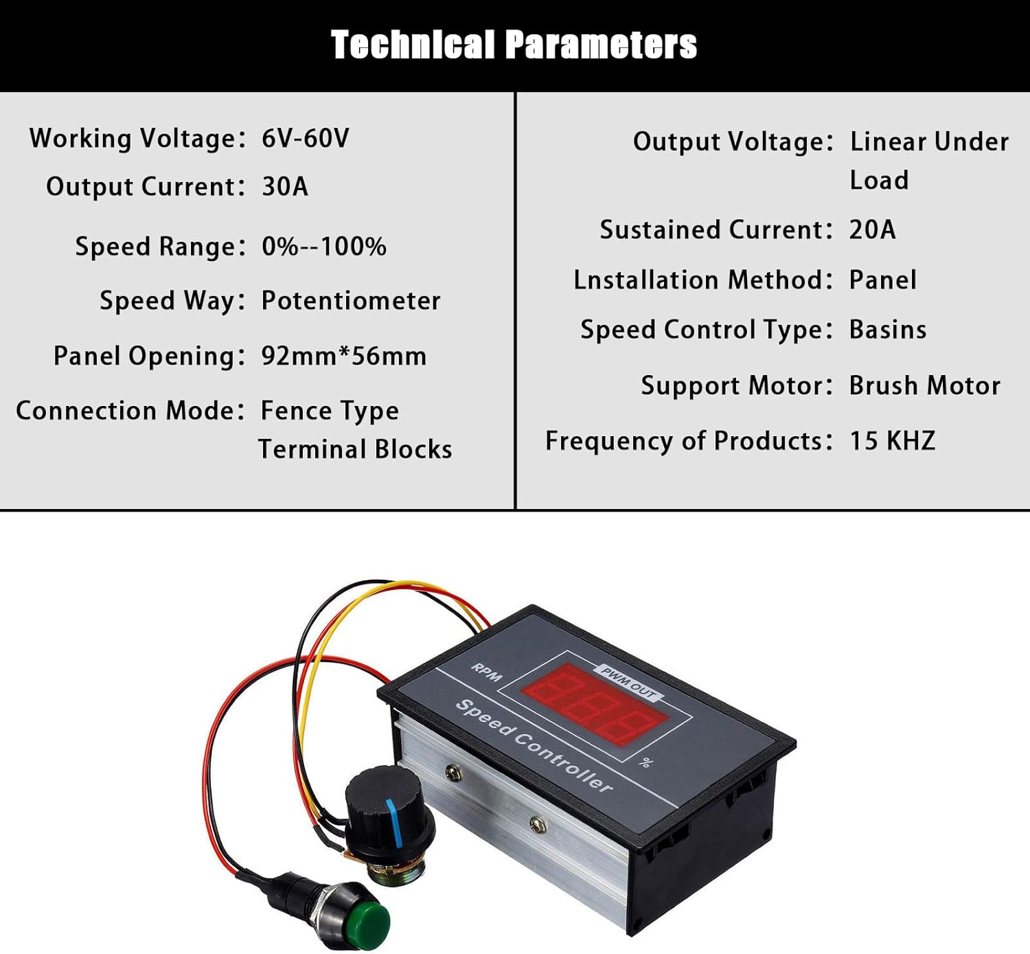
| പരാമീറ്റർ | മൂല്യം |
|---|---|
| വർക്കിംഗ് വോളിയംtage | DC 6V-60V |
| ഔട്ട്പുട്ട് കറൻ്റ് | 0A-30A |
| Sustained Current | 20എ |
| വേഗത പരിധി | 0% - 100% |
| വേഗത നിയന്ത്രണ തരം | പൊട്ടൻറ്റോമീറ്റർ |
| Support Motor | DC Brush Motor |
| പിഡബ്ല്യുഎം ഫ്രീക്വൻസി | 15 KHz |
| ഇൻസ്റ്റലേഷൻ രീതി | പാനൽ മ .ണ്ട് |
| Panel Opening Size | 92 മിമി x 56 മിമി |
| കണക്ഷൻ മോഡ് | Fence Type Terminal Blocks |
| മെറ്റീരിയൽ | ചെമ്പ് (ആന്തരിക ഘടകങ്ങൾ) |
| ഇനത്തിൻ്റെ ഭാരം | 1.41 ഔൺസ് (ഏകദേശം 0.04 കിലോഗ്രാം) |
| അളവുകൾ | 9.5 സെ.മീ x 6 സെ.മീ x 3.2 സെ.മീ (ഏകദേശം 3.74 ഇഞ്ച് x 2.36 ഇഞ്ച് x 1.25 ഇഞ്ച്) |

5. സജ്ജീകരണവും വയറിംഗും
Proper wiring is crucial for the safe and correct operation of the speed controller. Follow these steps carefully.
വയറിംഗ് ഡയഗ്രം:


കണക്ഷൻ ഘട്ടങ്ങൾ:
- പവർ ഇൻപുട്ട്: Connect your DC power supply (6V-60V) to the terminals labeled 'Power+' and 'Power-'. Ensure correct polarity.
- മോട്ടോർ ഔട്ട്പുട്ട്: Connect your DC brush motor to the terminals labeled 'Motor+' and 'Motor-'. The motor's rotation direction can be reversed by swapping these connections if needed.
- Potentiometer and Switch: The speed control potentiometer and start/stop switch are pre-wired to the main control unit. Ensure these connections are secure.

Use appropriate gauge wires for your application to handle the maximum current of 30A. Secure all connections firmly using the screw terminals.
6. ഓപ്പറേഷൻ
Once properly wired, operating the speed controller is straightforward.
- പവർ ഓൺ: Apply power to the controller. The LED digital display will illuminate, showing the current speed percentage (initially 0% if the motor is stopped).
- മോട്ടോർ ആരംഭിക്കുക: Press the green momentary start/stop button to start the motor. The display will show the current speed setting.
- വേഗത ക്രമീകരിക്കുക: Rotate the potentiometer knob clockwise to increase motor speed and counter-clockwise to decrease it. The LED display will update in real-time to show the new speed percentage.
- മോട്ടോർ നിർത്തുക: Press the green momentary start/stop button again to stop the motor. The display will show 0%.
The speed can be adjusted steplessly from 0% to 100% of the motor's maximum speed at the given input voltage.
7. പരിപാലനം
The Flylin DC Motor Speed Controller is designed for durability and requires minimal maintenance.
- വൃത്തിയാക്കൽ: Periodically clean the exterior of the controller with a dry, soft cloth. Do not use liquid cleaners or solvents.
- കണക്ഷനുകൾ: Regularly check all wiring connections to ensure they remain tight and secure. Loose connections can lead to intermittent operation or overheating.
- വെൻ്റിലേഷൻ: Ensure that the controller's housing is not obstructed, allowing for proper heat dissipation.
- പരിസ്ഥിതി വ്യവസ്ഥകൾ: Operate the controller within its specified environmental conditions (temperature, humidity) to prolong its lifespan.
8. പ്രശ്നപരിഹാരം
If you encounter issues with your speed controller, refer to the following troubleshooting guide:
| പ്രശ്നം | സാധ്യമായ കാരണം | പരിഹാരം |
|---|---|---|
| Controller does not power on / LED display is off. | No power input or incorrect wiring. | Check power supply connection and polarity. Ensure power source is active. |
| മോട്ടോർ ആരംഭിക്കുന്നില്ല. | Motor not connected, start/stop button not pressed, or potentiometer at 0%. | Verify motor connections. Press the start/stop button. Rotate potentiometer to increase speed. |
| മോട്ടോർ വേഗത ക്രമീകരിക്കാൻ കഴിയില്ല. | Potentiometer faulty or disconnected. | Check potentiometer connections. If faulty, replacement may be necessary. |
| Motor runs erratically or at incorrect speed. | Loose wiring, motor overload, or incompatible motor. | Check all wiring connections. Ensure motor current does not exceed 30A. Verify motor type is a DC brush motor. |
| Controller overheats. | Excessive load on motor, poor ventilation, or sustained current above 20A. | Reduce motor load. Ensure adequate ventilation around the controller. Avoid prolonged operation above 20A. |
9. വാറൻ്റിയും പിന്തുണയും
വാറന്റി വിവരങ്ങൾക്കോ സാങ്കേതിക പിന്തുണയ്ക്കോ, ദയവായി റീട്ടെയിലറെയോ നിർമ്മാതാവിന്റെയോ ഉദ്യോഗസ്ഥനെയോ കാണുക. webസൈറ്റ്. ഏതെങ്കിലും വാറന്റി ക്ലെയിമുകൾക്കായി നിങ്ങളുടെ വാങ്ങൽ രസീത് സൂക്ഷിക്കുക.