
MMSZ5V1CW
Zener Diode MMSZ5V1CW Instruction Manual
Model: MMSZ5V1CW
ആമുഖം
This manual provides essential information for the proper use and understanding of the Generic MMSZ5V1CW Zener Diode. This component is designed for voltage regulation and overvoltage protection in electronic circuits. It is crucial to understand its characteristics and proper handling to ensure optimal performance and circuit safety.
ഉൽപ്പന്നം കഴിഞ്ഞുview

Figure 1: Close-up of the MMSZ5V1CW Zener Diode. This image shows the compact SOD-123 package with visible markings, including "W8", which typically indicates the Zener voltage.
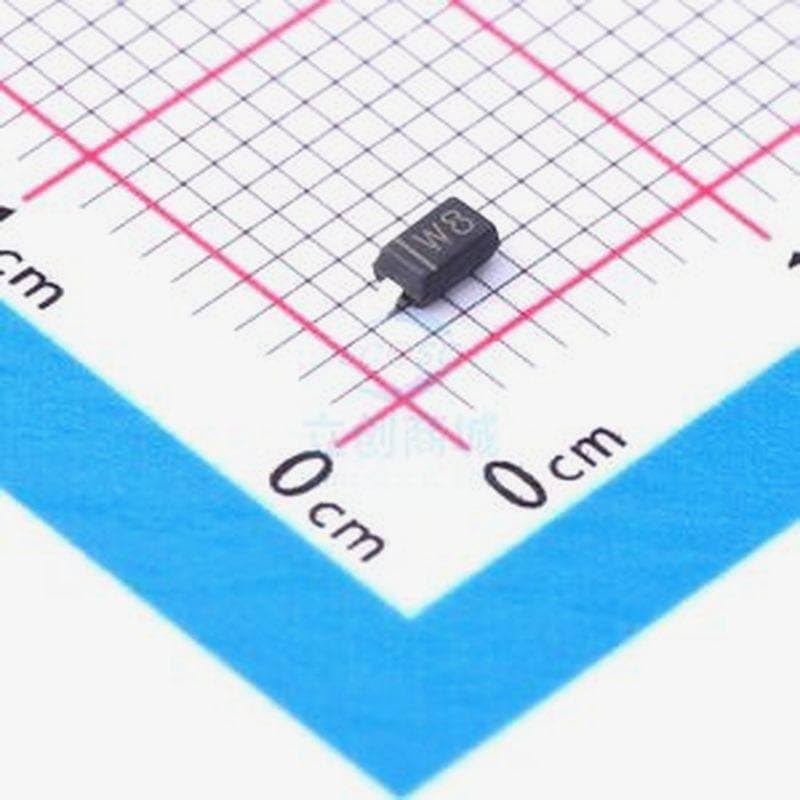
Figure 2: Zener Diode MMSZ5V1CW on a centimeter grid. This image illustrates the small physical dimensions of the diode, approximately 2.5mm in length, highlighting its suitability for compact circuit designs.
സജ്ജീകരണവും ഇൻസ്റ്റാളേഷനും
The MMSZ5V1CW Zener diode is a surface-mount device (SMD) in a SOD-123 package. Proper installation requires careful handling and soldering techniques.
- പോളാരിറ്റി തിരിച്ചറിയുക: Zener diodes are polarized components. The cathode (negative) end is typically marked with a band or line on the diode body. Ensure correct orientation before soldering. Incorrect polarity can lead to circuit malfunction or damage to the diode.
- Prepare PCB Pads: Ensure the solder pads on your Printed Circuit Board (PCB) are clean and free of oxidation.
- പ്ലേസ്മെൻ്റ്: Carefully place the diode onto the designated pads, aligning the cathode band with the corresponding marking on the PCB layout.
- സോൾഡറിംഗ്: Use appropriate soldering equipment (e.g., fine-tip soldering iron, hot air station) and lead-free solder. Apply heat to the pad and component lead simultaneously, then feed solder. Avoid excessive heat, which can damage the diode.
- പരിശോധന: After soldering, visually inspect the connections for good solder joints (smooth, shiny fillets) and correct alignment.
For detailed soldering instructions, refer to industry standards for SMD component assembly.
പ്രവർത്തന തത്വങ്ങൾ
The Zener diode is designed to operate in reverse bias. When the reverse voltage across the diode reaches its Zener voltage (Vz), it begins to conduct current, maintaining a relatively constant voltage across its terminals despite variations in current or input voltage. This characteristic makes it ideal for voltagഇ നിയന്ത്രണം.
- വാല്യംtagഇ നിയന്ത്രണം: In a voltage regulator circuit, the Zener diode is connected in parallel with the load and in series with a current-limiting resistor. It clampഔട്ട്പുട്ട് വോള്യംtage to its Zener voltage.
- ഓവർ വോൾtagഇ സംരക്ഷണം: ഒരു ഇൻപുട്ട് വോളിയം എപ്പോൾtage exceeds the Zener voltage, the diode conducts heavily, diverting excess current and protecting sensitive components from damage.
- നിലവിലെ പരിമിതി: A series resistor is always required to limit the current through the Zener diode to prevent thermal runaway and damage.
മെയിൻ്റനൻസ്
Zener diodes are solid-state electronic components and typically require no routine maintenance once properly installed. Ensure the operating environment is within specified temperature and humidity ranges to prevent premature failure. Avoid exposing the diode to excessive mechanical stress or corrosive substances.
ട്രബിൾഷൂട്ടിംഗ്
If your circuit involving the Zener diode is not functioning as expected, consider the following common issues:
- തെറ്റായ പോളാരിറ്റി: Verify that the Zener diode is installed with the correct polarity (cathode band aligned). A reverse-biased Zener diode will not regulate voltagഇ ശരിയായി.
- Insufficient Current Limiting Resistor: If the series resistor is too small, excessive current can flow through the diode, causing it to overheat and fail. Calculate the appropriate resistor value based on the input voltage, Zener voltage, and desired Zener current.
- Exceeded Power Dissipation: Ensure the power dissipated by the Zener diode (Vz * Iz) does not exceed its maximum power rating. Over-dissipation will lead to thermal damage.
- Incorrect Zener Voltage: Confirm that the Zener voltage of the diode (MMSZ5V1CW is 5.1V) matches the requirements of your circuit.
- Poor Solder Joints: Inspect solder connections for cold joints, bridges, or open circuits. Re-solder if necessary.
സ്പെസിഫിക്കേഷനുകൾ
| സ്വഭാവം | മൂല്യം |
|---|---|
| സെനർ വോളിയംtage (Vz) | 5.1V |
| പാക്കേജ് തരം | SOD-123 |
| അളവ് | 50 പിസിഎസ് |
| നിർമ്മാതാവ് | ജനറിക് |
| ASIN | B0D6SSP1D2 |
| ആദ്യ തീയതി ലഭ്യമാണ് | ജൂൺ 11, 2024 |
Note: For detailed electrical characteristics and absolute maximum ratings, refer to the manufacturer's datasheet for the MMSZ5V1CW Zener diode.
വാറൻ്റിയും പിന്തുണയും
As a standard electronic component, specific warranty details are typically provided by the distributor or seller at the time of purchase. For technical support or inquiries regarding the MMSZ5V1CW Zener diode, please contact your supplier or refer to the manufacturer's official documentation.
This product is intended for use by individuals with appropriate knowledge of electronics and circuit design. Improper use or handling may result in damage to the component or associated circuitry.
Ask a question about this manual
Ask about setup, troubleshooting, compatibility, parts, safety, or missing instructions. Manuals+ will review the question and use this page’s manual context to help answer it.