
1. ആമുഖം
The FNIRSI DST-210 is a compact and versatile 3-in-1 handheld device designed for electronic testing and measurement. It integrates the functions of a digital oscilloscope, a true RMS multimeter, and a signal generator into a single portable unit. This manual provides detailed instructions to help you effectively use and maintain your device.
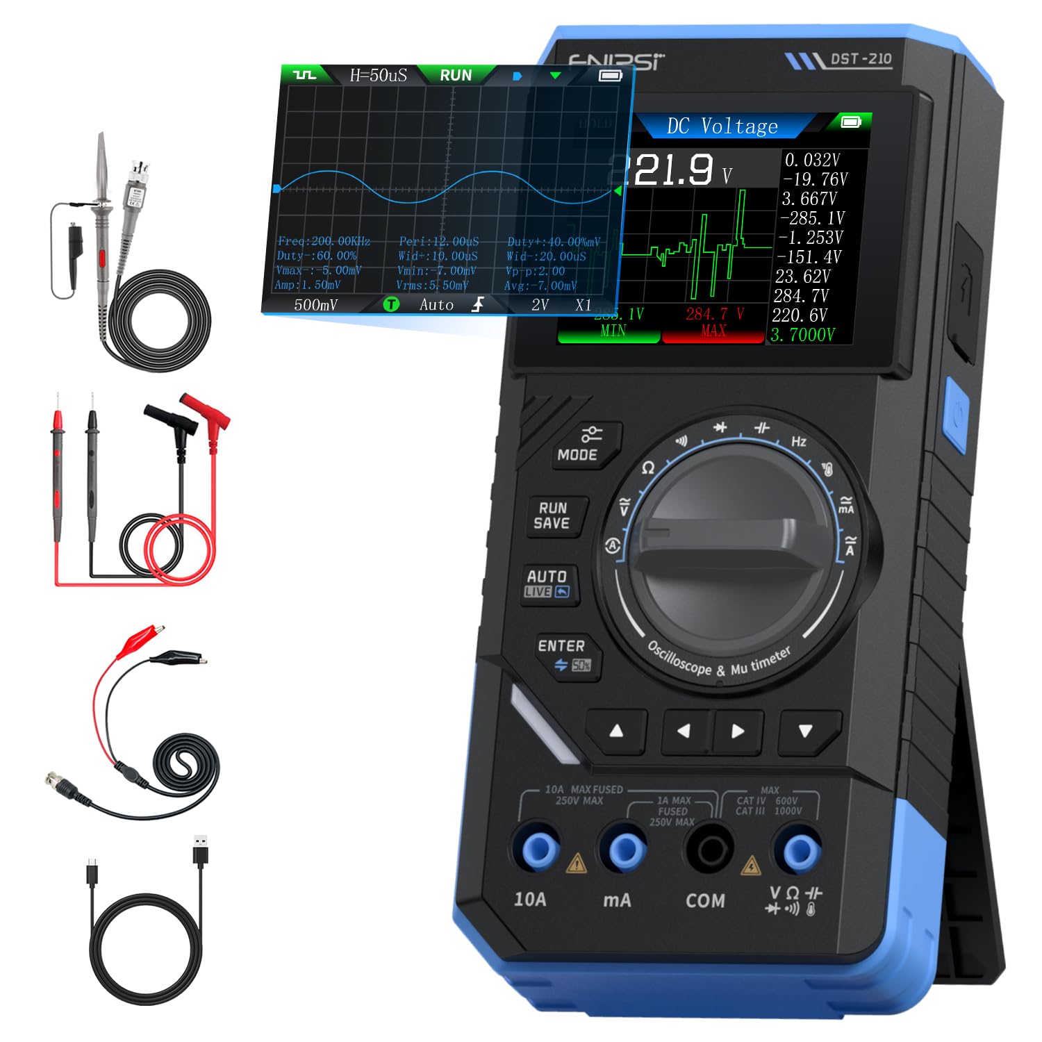
Figure 1: FNIRSI DST-210 3-in-1 Handheld Device
2. ഉൽപ്പന്നം കഴിഞ്ഞുview
2.1 പ്രധാന സവിശേഷതകൾ
- 3-ഇൻ-1 പ്രവർത്തനം: Combines a digital oscilloscope, a true RMS multimeter, and a signal generator.
- ഡിസ്പ്ലേ: 2.8-inch TFT color LCD for clear data visualization.
- ഓസിലോസ്കോപ്പ്: 10MHz analog bandwidth, 48MSa/s real-time sampling rate, supports Auto/Normal/Single trigger modes, waveform image saving and display.
- മൾട്ടിമീറ്റർ: 19999-count true RMS measurement for DC/AC voltage, DC/AC current, resistance, capacitance, frequency, temperature, diode, and continuity. Features data hold, record mode with graphical display, and LIVE function for voltage presence detection.
- സിഗ്നൽ ജനറേറ്റർ: Outputs 13 types of waveforms (Sine, Square, Sawtooth, Half-wave, Full-wave, Step, Reverse Step, Index Up/Down, DC, Multi-audio, Sink Pulse, Lorentz Wave) with adjustable frequency (0-50KHz), amplitude (0.1-3.0V), and duty cycle (0-100%).
- പോർട്ടബിലിറ്റി: Compact design with an integrated stand, powered by a 3000mAh rechargeable lithium battery providing up to 10 hours of continuous use. Type-C charging supported.
2.2 പാക്കേജ് ഉള്ളടക്കം
പാക്കേജിൽ എല്ലാ ഇനങ്ങളും ഉണ്ടെന്ന് ഉറപ്പാക്കുക:
- FNIRSI DST-210 Main Unit
- P6100 High Voltagഇ പ്രോബ്
- ടെസ്റ്റ് ലീഡുകൾ (ചുവപ്പും കറുപ്പും)
- അലിഗേറ്റർ ക്ലിപ്പുകൾ
- ടൈപ്പ്-സി ചാർജിംഗ് കേബിൾ
- Instruction Manual (PDF version available online)
- പാക്കേജിംഗ് ബോക്സ്

ചിത്രം 2: ഉൾപ്പെടുത്തിയ ആക്സസറികൾ
3. സജ്ജീകരണം
3.1 ഉപകരണം ചാർജ് ചെയ്യുന്നു
Before initial use, fully charge the DST-210. Connect the provided Type-C charging cable to the device's Type-C port and a compatible USB power adapter (5V/1A). The battery indicator on the display will show charging status.
3.2 കണക്ടിംഗ് പ്രോബുകൾ
For accurate measurements, ensure probes are correctly connected:
- Multimeter Measurements: Insert the red test lead into the VΩHzmA or 10A jack (depending on the measurement) and the black test lead into the COM jack.
- Oscilloscope Measurements: Connect the P6100 high voltage probe to the oscilloscope input jack. Ensure the probe's attenuation setting (e.g., X1 or X10) matches the device's setting for accurate readings.
- Signal Generator Output: Connect the output cable to the signal generator output port.

Figure 3: Input Jacks and Controls
4. പ്രവർത്തന നിർദ്ദേശങ്ങൾ
4.1 പവർ ഓൺ/ഓഫ്
Press and hold the power button (located on the side) to turn the device on or off.
4.2 മോഡ് തിരഞ്ഞെടുക്കൽ
Rotate the central knob to switch between Multimeter, Oscilloscope, and Signal Generator modes. Within each mode, further sub-functions can be selected using the knob or dedicated buttons.

Figure 4: Using the Oscilloscope Function
4.3 മൾട്ടിമീറ്റർ പ്രവർത്തനം
In Multimeter mode, the device offers various measurement functions:
- വാല്യംtage/Current (DC/AC): Select the appropriate DC V, AC V, DC A, or AC A setting. Connect test leads to the circuit. The device supports a record mode that displays measurement trends graphically, and can store up to 10 sets of data.
- പ്രതിരോധം (Ω): Select the resistance function. Connect test leads across the component.
- കപ്പാസിറ്റൻസ് (F): Select the capacitance function. Connect test leads across the capacitor.
- ആവൃത്തി (Hz): Select the frequency function. Connect test leads to the signal source.
- ഡയോഡ് ടെസ്റ്റ്: Select the diode function. Connect test leads across the diode to check its forward voltagഇ ഡ്രോപ്പ്.
- തുടർച്ച പരിശോധന: Select the continuity function. Connect test leads across a conductor; a beep indicates continuity.
- താപനില: Use a K-type thermocouple (not included) connected to the appropriate jacks for temperature measurement.
- LIVE Function: For single-probe voltage presence detection.

Figure 5: Multimeter Measurement Exampലെസ്
4.4 ഓസിലോസ്കോപ്പ് പ്രവർത്തനം
In Oscilloscope mode, the device displays waveforms:
- തരംഗരൂപ പ്രദർശനം: Connect the oscilloscope probe to the circuit. The device automatically adjusts settings for stable waveform display.
- ട്രിഗർ മോഡുകൾ: Select between Auto, Normal, and Single trigger modes to capture different types of signals.
- Waveform Saving: Press the 'RUN/SAVE' button to save the current waveform image. Saved images can be reviewഎഡിറ്റ് ചെയ്ത് കയറ്റുമതി ചെയ്തു.

Figure 6: Oscilloscope Waveform Display
4.5 Signal Generator Operation
In Signal Generator mode, the device outputs various waveforms:
- തരംഗരൂപ തിരഞ്ഞെടുപ്പ്: Choose from 13 different waveform types using the menu options.
- പാരാമീറ്റർ അഡ്ജസ്റ്റ്മെന്റ്: Adjust the frequency (0-50KHz), amplitude (0.1-3.0V), and duty cycle (0-100%) as required for your application.

Figure 7: Signal Generator Waveform Selection
4.6 PC Connection and Data Export
The DST-210 can connect to a PC via its Type-C USB port for data management and firmware updates.
- Waveform Screenshots: Long-press the 'RUN/SAVE' button to save waveform screenshots.
- ഡാറ്റ കയറ്റുമതി: Connect the device to a computer to view, save, and export recorded waveform images and data.
- ഫേംവെയർ അപ്ഡേറ്റുകൾ: Periodically check the official FNIRSI webഒപ്റ്റിമൽ പ്രകടനവും പുതിയ സവിശേഷതകളിലേക്കുള്ള ആക്സസും ഉറപ്പാക്കാൻ ഫേംവെയർ അപ്ഡേറ്റുകൾക്കായി സൈറ്റ്. ഫേംവെയർ അപ്ഡേറ്റ് പാക്കേജിനൊപ്പം നൽകിയിരിക്കുന്ന നിർദ്ദേശങ്ങൾ പാലിക്കുക.

Figure 8: PC Connection for Data Management
5. പരിപാലനം
- വൃത്തിയാക്കൽ: ഉപകരണം വൃത്തിയാക്കാൻ മൃദുവായതും ഉണങ്ങിയതുമായ തുണി ഉപയോഗിക്കുക. അബ്രസീവ് ക്ലീനറുകളോ ലായകങ്ങളോ ഉപയോഗിക്കരുത്.
- സംഭരണം: നേരിട്ടുള്ള സൂര്യപ്രകാശത്തിൽ നിന്നും കടുത്ത താപനിലയിൽ നിന്നും മാറി തണുത്തതും വരണ്ടതുമായ സ്ഥലത്ത് ഉപകരണം സൂക്ഷിക്കുക.
- ബാറ്ററി കെയർ: ബാറ്ററി ലൈഫ് വർദ്ധിപ്പിക്കാൻ, ബാറ്ററി ഇടയ്ക്കിടെ പൂർണ്ണമായും ഡിസ്ചാർജ് ചെയ്യുന്നത് ഒഴിവാക്കുക. ദീർഘനേരം ഉപയോഗത്തിലില്ലെങ്കിൽ പോലും ഉപകരണം പതിവായി ചാർജ് ചെയ്യുക.
- പ്രോബ് കെയർ: Inspect test leads and probes for damage before each use. Replace any damaged accessories immediately.
6. പ്രശ്നപരിഹാരം
| പ്രശ്നം | സാധ്യമായ കാരണം | പരിഹാരം |
|---|---|---|
| ഉപകരണം പവർ ഓണാക്കുന്നില്ല. | ബാറ്ററി കുറവാണോ അതോ പവർ ബട്ടൺ തകരാറിലാണോ. | Charge the device fully. If the issue persists, contact support. |
| Unstable or inaccurate readings in Multimeter mode. | Poor probe connection, incorrect mode selection, or external interference. | Ensure probes are securely connected. Verify the correct measurement mode is selected. Minimize external electrical interference. |
| Oscilloscope waveform is not stable. | Incorrect trigger settings or probe attenuation. | Adjust trigger level and mode. Ensure probe attenuation (X1/X10) matches the device setting. |
| Signal generator output is incorrect. | Incorrect waveform type, frequency, amplitude, or duty cycle settings. | Verify all signal generator parameters are set as desired. |
| Cannot connect to PC or export data. | Faulty USB cable, incorrect PC driver, or software issue. | Try a different Type-C cable. Ensure necessary drivers are installed on your PC. Refer to the official website for software and driver downloads. |
7 സ്പെസിഫിക്കേഷനുകൾ
7.1 ഓസിലോസ്കോപ്പ് പാരാമീറ്ററുകൾ
| വിഭാഗം | സ്പെസിഫിക്കേഷൻ |
|---|---|
| തത്സമയ എസ്ampലിംഗ് നിരക്ക് | 48 എംഎസ്എ / സെ |
| അനലോഗ് ബാൻഡ്വിഡ്ത്ത് | 10MHz |
| ഇൻപുട്ട് ഇംപെഡൻസ് | 1MΩ |
| കപ്ലിംഗ് രീതി | എസി/ഡിസി |
| അളവ് വോളിയംtagഇ റേഞ്ച് | 1:1 Probe: ±80Vpp (±40V), 10:1 Probe: ±800Vpp (±400V) |
| ലംബ സംവേദനക്ഷമത | 10mV/div ~ 10V/div (at X1) |
| ലംബമായ ഓഫ്സെറ്റ് | Adjustable (with indicator) |
| Horizontal Time Base Range | 50 സെ ~ 20 സെ |
| ട്രിഗർ മോഡ് | ഓട്ടോ, നോർമൽ, സിംഗിൾ |
| എഡ്ജ് ട്രിഗർ | Rising/Falling Edge |
| ട്രിഗർ ലെവൽ | Adjustable (with indicator) |
| വേവ്ഫോം ഫ്രീസ് | Supported (HOLD function) |
| യാന്ത്രിക അളവ് | Max, Min, Average, RMS, Peak-to-Peak, Frequency, Duty Cycle, etc. |
7.2 മൾട്ടിമീറ്റർ പാരാമീറ്ററുകൾ
| അളക്കൽ പ്രവർത്തനം | പരിധി | കൃത്യത |
|---|---|---|
| ഡിസി വോളിയംtage | 1.9999V/19.999V/199.99V/1000V | ±(0.5%+3) |
| എസി വോളിയംtage | 1.9999V/19.999V/199.99V/750V | ±(1.0%+3) |
| ഡിസി കറൻ്റ് | 19.999mA/199.99mA/1.9999A/9.999A | ±(1.2%+3) |
| എസി കറന്റ് | 19.999mA/199.99mA/1.9999A/9.999A | ±(1.5%+3) |
| പ്രതിരോധം | 19.999MΩ/199.99kΩ/19.999kΩ | ±(2.0%+5) |
| കപ്പാസിറ്റൻസ് | 999.9uF/99.99uF/9.999uF/999.9nF/99.99nF, 9.999mF/99.99mF | ±(2.0%+5) |
| ആവൃത്തി | 9.999MHz/999.9kHz/99.99kHz/9.999kHz/999.9Hz/99.99Hz | ±(0.1%+2) |
| താപനില | [-55~1300°C] / [-67~2372°F] | ±(2.5%+5) |
| ഡയോഡ്/തുടർച്ച | പിന്തുണച്ചു | N/A |
| LIVE Function | പിന്തുണച്ചു | N/A |
7.3 സിഗ്നൽ ജനറേറ്റർ പാരാമീറ്ററുകൾ
| വിഭാഗം | സ്പെസിഫിക്കേഷൻ |
|---|---|
| Output Waveforms | 13 തരം |
| വേവ്ഫോം ഫ്രീക്വൻസി | 0 ~ 50KHz |
| ഡ്യൂട്ടി സൈക്കിൾ | 0 ~ 100% (adjustable) |
| തരംഗരൂപം Ampഅക്ഷാംശം | 0.1 ~ 3.0V |
7.4 പൊതു സവിശേഷതകൾ
| വിഭാഗം | സ്പെസിഫിക്കേഷൻ |
|---|---|
| ഉൽപ്പന്ന മോഡൽ | DST-210 |
| പ്രദർശിപ്പിക്കുക | 2.8-inch TFT Color Display |
| ബാക്ക്ലൈറ്റ് | തെളിച്ചം ക്രമീകരിക്കാവുന്ന |
| വൈദ്യുതി വിതരണം | ടൈപ്പ്-സി (5V/1A) |
| ബാറ്ററി | 3000mAh |
| ഭാഷാ പിന്തുണ | ചൈനീസ്, ഇംഗ്ലീഷ് |
| ഉൽപ്പന്ന വലുപ്പം | ഏകദേശം 177.43 mm x 87 mm x 35 mm |
| ഉൽപ്പന്ന ഭാരം | ഏകദേശം 300 ഗ്രാം |
8. വാറൻ്റിയും പിന്തുണയും
For any questions, issues, or support needs regarding your FNIRSI DST-210, please contact us through the following methods:
- ആമസോൺ സന്ദേശം: If you purchased the product on Amazon, you can contact us via the Amazon messaging system. Go to your 'Order History', select the relevant order, and click 'Problem with order' or 'Contact Seller'.
- ഇമെയിൽ പിന്തുണ: You can also reach our after-sales service center directly via email at support@fnirsi.com. Please include your order number and a detailed description of your issue for faster assistance.
When attaching large photos or videos, email support is recommended due to potential attachment size limits on Amazon's messaging system.
Video 1: Demonstration of FNIRSI DST-210's Multimeter, Oscilloscope, and Signal Generator Functions.