
1 പ്രധാനപ്പെട്ട സുരക്ഷാ വിവരങ്ങൾ
This Variable Frequency Drive (VFD) is designed for controlling three-phase asynchronous motors. Adhere to all safety precautions during installation, operation, and maintenance to prevent injury or equipment damage.
- മോട്ടോർ അനുയോജ്യത: This VFD is ONLY applicable to three-phase asynchronous motors.
- Horsepower Selection: If your motor operates under heavy load, select a VFD with higher horsepower than your motor's rating.
- Air Compressor Application: For air compressors, due to large instantaneous starting currents, select a VFD with twice the horsepower of the motor. For example, a 2 HP compressor requires a 4 HP or 5 HP VFD.
- Soft-Start Function: The VFD provides a soft-start capability to prevent high current surges to the power grid and mechanical shock to the machine system. Do NOT start the motor directly after the VFD is powered on.
- VFD യുടെയും മോട്ടോറിന്റെയും ശരിയായ ഗ്രൗണ്ടിംഗ് ഉറപ്പാക്കുക.
- All electrical work should be performed by qualified personnel.
2. ഉൽപ്പന്നം കഴിഞ്ഞുview ഫീച്ചറുകളും
The LAPOND K100-022G1 VFD is a high-performance inverter designed for precise motor control. It features robust construction and advanced functionalities for various industrial and home applications.
പ്രധാന സവിശേഷതകൾ:
- ഇൻപുട്ട്/ഔട്ട്പുട്ട്: 1-phase/3-phase 220VAC input (±15%, 50/60Hz); 3-phase 220VAC output (0-400Hz, 22KW).
- മോട്ടോർ അനുയോജ്യത: Suitable for ≤25HP (18kW) 75Amps 200-230V 3-Phase Motors.
- സ ible കര്യപ്രദമായ പ്രവർത്തനം: Enhanced digital/analog terminals for flexible control, supporting Mach3 function & RS-485 communication (no 485 card required), remote potentiometer, switch start/stop, and braking resistor.
- ഉയർന്ന പ്രകടനം: Utilizes high stability, low failure rate IGBT modules, ensuring superior performance and stability with low noise.
- കാര്യക്ഷമമായ തണുപ്പിക്കൽ: Built-in cooling fan and multi-grid design with copper coils ensure excellent heat dissipation and durability.
- ഉപയോക്തൃ-സൗഹൃദ ഇൻ്റർഫേസ്: Display and keys enable quick setup. Detachable panel allows for remote control and easy installation.
- കരുത്തുറ്റ നിർമ്മാണം: Made from flame-retardant material for high impact resistance and heat resistance.
- Full Chip Design: All internal components are designed as chips, greatly increasing the stability of the VFD.

Figure 2.1: LAPOND K100-022G1 Variable Frequency Drive unit.
3. പാക്കേജ് ഉള്ളടക്കം
പാക്കേജിൽ എല്ലാ ഇനങ്ങളും ഉണ്ടെന്ന് ഉറപ്പാക്കുക:
- LAPOND K100-022G1 VFD Inverter
- ഉപയോക്തൃ മാനുവൽ (ഈ പ്രമാണം)
4 സ്പെസിഫിക്കേഷനുകൾ
| പരാമീറ്റർ | മൂല്യം |
|---|---|
| ബ്രാൻഡ് | ലാപോണ്ട് |
| മോഡൽ നമ്പർ | K100-022G1 |
| ഇൻപുട്ട് വോളിയംtage | 220V AC (1-phase/3-phase) |
| Putട്ട്പുട്ട് വോളിയംtage | 220V AC (3-phase) |
| ഔട്ട്പുട്ട് പവർ | 22 KW / 30 HP |
| ഔട്ട്പുട്ട് കറൻ്റ് | 90എ |
| ഫ്രീക്വൻസി റേഞ്ച് | 0-400 Hz |
| അളവുകൾ (L x W x H) | 10.63" x 8" x 19.3" |
| ഇനത്തിൻ്റെ ഭാരം | 33 പൗണ്ട് |
| ഡിസ്പ്ലേ തരം | ഡിജിറ്റൽ |
| ശുപാർശ ചെയ്യുന്ന ഉപയോഗങ്ങൾ | Mixer, pump, compressor, conveyor, elevator, ventilator, grinder, milling machine, drilling machine, CNC router, extruder, slitter, winder, blower, hoist, centrifuge, winding machine, etc. |
5. ഇൻസ്റ്റലേഷനും വയറിംഗും
Proper installation and wiring are crucial for the safe and efficient operation of the VFD. Refer to the following diagrams and instructions.
5.1 Terminal Control Overview

Figure 5.1: Internal terminal block for control wiring. This section includes connections for +10V, GND, RS485+, RS485-, AI1, AI2, AO1, COM, DI1, DI2, DI3.
The VFD features a comprehensive terminal block for various control inputs and outputs. These include analog inputs (AI1, AI2), analog output (AO1), digital inputs (DI1, DI2, DI3), and communication ports (RS485). Ensure all connections are secure and correctly identified according to the full wiring diagram in the detailed manual.
5.2 Power and Motor Wiring Diagram (4KW-15KW Exampലെ)
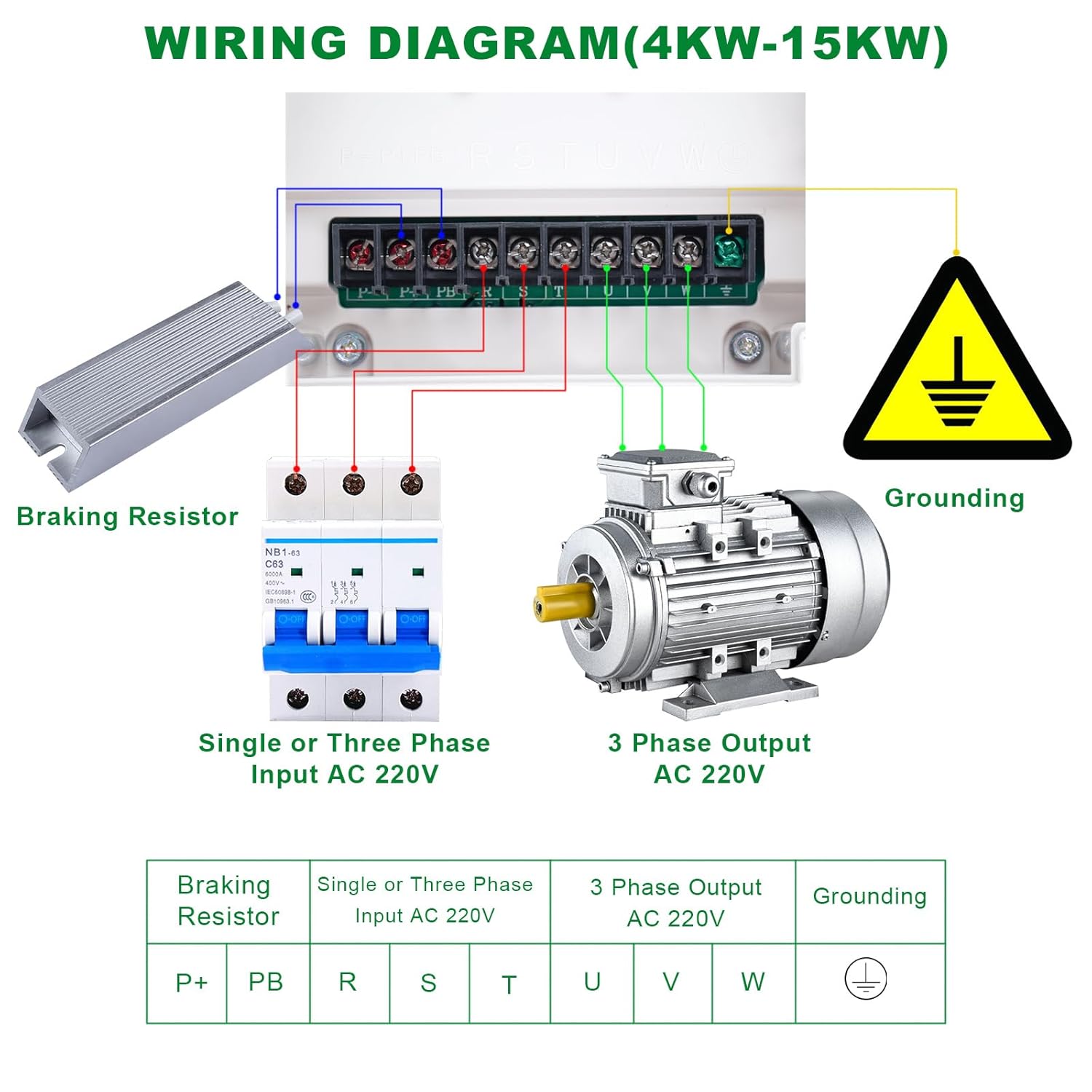
ചിത്രം 5.2: ഉദാample wiring diagram for VFD models between 4KW and 15KW. This diagram illustrates connections for single or three-phase AC 220V input, 3-phase AC 220V output to the motor, grounding, and an optional braking resistor.
Input Power (R, S, T): Connect the AC 220V single or three-phase power supply to the R, S, T terminals. For single-phase input, connect to R and S (or R and T) as per the detailed manual. Ensure a circuit breaker is installed upstream for protection.
മോട്ടോറിലേക്കുള്ള ഔട്ട്പുട്ട് (U, V, W): Connect the three-phase motor to the U, V, W terminals. Ensure correct phase sequence for desired motor rotation.
ഗ്രൗണ്ടിംഗ്: Connect the grounding terminal (marked with earth symbol) to a reliable earth ground. This is critical for safety.
Braking Resistor (P+, PB): For applications requiring rapid deceleration, connect an external braking resistor between P+ and PB terminals. Refer to the VFD's specifications for appropriate resistor values.
Note: The provided diagram is an example for 4KW-15KW models. For the 22KW/30HP model, ensure to consult the specific wiring instructions in the comprehensive manual for terminal designations and current ratings.
6. പ്രവർത്തന നിർദ്ദേശങ്ങൾ
The VFD features a user-friendly control panel for setting parameters and operating the motor.
6.1 നിയന്ത്രണ പാനൽ ലേഔട്ട്

ചിത്രം 6.1: വിശദമായി view of the VFD control panel with numbered components.
- ഫ്രീക്വൻസി നോബ്: Adjusts the output frequency, thereby controlling motor speed.
- റൺ കീ: മോട്ടോർ പ്രവർത്തനം ആരംഭിക്കുന്നു.
- നിർത്തുക/പുനഃസജ്ജമാക്കുക കീ: Stops motor operation or resets fault conditions.
- PRG (Program) Key: Enters or exits the parameter programming menu.
- Shift Key (>>): Moves the cursor or shifts digits during parameter editing.
- Numerical Modification Key (Up Arrow): Increases numerical values or scrolls up through menu options.
- Numerical Modification Key (Down Arrow): Decreases numerical values or scrolls down through menu options.
- FUNC (Function) Key: Selects according to function toggle.
- എന്റർ കീ: Confirms parameter settings or menu selections.
6.2 അടിസ്ഥാന പ്രവർത്തന ഘട്ടങ്ങൾ
- പവർ ഓൺ: Ensure all wiring is correct and secure. Apply power to the VFD.
- പാരാമീറ്റർ സജ്ജീകരണം: അമർത്തുക പി.ആർ.ജി key to enter the parameter menu. Use the Up/Down arrow keys to navigate through parameters and the Shift key to move between digits. Use the പ്രവേശിക്കുക key to confirm changes. Refer to the detailed manual for specific parameter settings (e.g., motor parameters, acceleration/deceleration times).
- ഫ്രീക്വൻസി അഡ്ജസ്റ്റ്മെന്റ്: ഉപയോഗിക്കുക Frequency Knob to set the desired output frequency (motor speed).
- മോട്ടോർ ആരംഭിക്കുക: അമർത്തുക പ്രവർത്തിപ്പിക്കുക key to start the motor. The motor will accelerate to the set frequency according to the programmed acceleration time.
- മോട്ടോർ നിർത്തുക: അമർത്തുക നിർത്തുക/പുനSEസജ്ജമാക്കുക key to stop the motor. The motor will decelerate according to the programmed deceleration time.
For advanced functions, such as external control, Mach3 integration, or RS-485 communication, refer to the detailed programming guide in the complete user manual.
6.3 Removable Operation Panel

Figure 6.2: The VFD unit with its removable operation panel, allowing for remote control and flexible installation.
The VFD's operation panel can be detached from the main unit and mounted remotely. This feature provides flexibility in installation and allows for convenient control from a distance. Ensure the connection cable is securely attached when using the panel remotely.
7. Protections and Internal Design
The LAPOND VFD incorporates multiple protection mechanisms and a robust internal design to ensure reliable and safe operation.
7.1 ബിൽറ്റ്-ഇൻ പരിരക്ഷകൾ

Figure 7.1: Visual representation of the nine protection features integrated into the VFD.
- ഓവർ വോൾtagഇ സംരക്ഷണം: അമിതമായ ഇൻപുട്ട് വോള്യത്തിനെതിരായ സുരക്ഷാ മുൻകരുതലുകൾtage.
- അണ്ടർവോൾtagഇ സംരക്ഷണം: Prevents operation during insufficient input voltage.
- ഓവർകറന്റ് സംരക്ഷണം: Protects the VFD and motor from excessive current draw.
- ഓവർലോഡ് സംരക്ഷണം: Monitors motor load and prevents damage from sustained overloads.
- താപനില സംരക്ഷണം: Prevents overheating of the VFD components.
- Module Protection: Protects internal power modules (IGBTs).
- ഭൂസംരക്ഷണം: Ensures safety in case of ground faults.
- ഷോർട്ട് സർക്യൂട്ട് സംരക്ഷണം: Detects and reacts to short circuits in the output.
- Phase Protection: Monitors input/output phases for anomalies.
7.2 Internal Design and Cooling

Figure 7.2: Internal components and design features of the VFD, highlighting the mainboard, full chip design, flame-retardant casing, and cooling fan.
- Newest Mainboard: Features an extremely protective and fully functional mainboard.
- Full Chip Design: All internal components are designed as chips, significantly increasing the stability and reliability of the VFD.
- ജ്വാല പ്രതിരോധക വസ്തു: The VFD casing is constructed from high-impact and heat-resistant flame-retardant material for enhanced safety.
- Powerful Cooling Fan: A low-noise, durable, and powerful cooling fan is integrated to ensure efficient heat dissipation, maintaining optimal operating temperatures.
8. പരിപാലനം
Regular maintenance helps ensure the longevity and optimal performance of your VFD.
- വൃത്തിയാക്കൽ: Periodically clean the VFD's exterior and cooling fan vents to prevent dust accumulation, which can hinder heat dissipation. Use a soft, dry cloth. Do not use liquid cleaners.
- പരിശോധനകൾ: Regularly inspect all wiring connections for tightness and signs of wear or damage. Check for any unusual noises or odors during operation.
- പരിസ്ഥിതി വ്യവസ്ഥകൾ: Ensure the VFD operates within its specified environmental conditions (temperature, humidity, dust level).
- ഫാൻ പരിശോധന: Verify that the cooling fan is operating correctly when the VFD is running. A non-functional fan can lead to overheating.
- കപ്പാസിറ്റർ ലൈഫ്: Electrolytic capacitors have a finite lifespan. While designed for durability, consider professional inspection after several years of continuous operation.
9. പ്രശ്നപരിഹാരം
This section provides basic troubleshooting steps for common issues. For complex problems, consult a qualified technician or the manufacturer's support.
- VFD Does Not Power On:
- Check input power supply and circuit breaker.
- Verify all power wiring connections are secure.
- മോട്ടോർ സ്റ്റാർട്ട് ആകുന്നില്ല:
- Check if the VFD is displaying any fault codes. Refer to the detailed manual for fault code explanations.
- Ensure the RUN command is active (either from the control panel or external input).
- Verify motor wiring (U, V, W) is correct and secure.
- Check motor parameters in the VFD settings.
- Motor Runs at Incorrect Speed:
- Verify the frequency setting on the control panel or external potentiometer.
- Check motor nameplate data and VFD motor parameters (e.g., rated frequency, poles).
- VFD Trips Frequently (Overcurrent, Overload, etc.):
- Check for mechanical issues with the motor or driven equipment (e.g., binding, excessive load).
- Ensure the VFD's horsepower rating is appropriate for the motor and application, especially for heavy loads or air compressors (as noted in Safety Information).
- Review acceleration/deceleration times; increasing them might reduce current spikes.
- Check for proper ventilation and ensure the cooling fan is operating.
10. വാറൻ്റിയും പിന്തുണയും
വാറൻ്റി കാലയളവ്: This LAPOND VFD is covered by a 1 വർഷത്തെ വാറൻ്റി വാങ്ങിയ തീയതി മുതൽ.
The warranty covers defects in materials and workmanship under normal use. It does not cover damage resulting from improper installation, misuse, unauthorized modifications, or external factors such as power surges or natural disasters.
For warranty claims, technical support, or service inquiries, please contact LAPOND customer service through your purchase platform or the official LAPOND website. Please have your model number (K100-022G1) and purchase details ready.