
1. ആമുഖം
The FNIRSI 1014D is a versatile 2-in-1 device, combining a digital oscilloscope with a DDS (Direct Digital Synthesis) function signal generator. Designed for a wide range of applications from electronic DIY to scientific research, this instrument offers powerful features for waveform analysis and signal generation. This manual provides essential information for the safe and effective operation, setup, and maintenance of your FNIRSI 1014D.

Image 1.1: FNIRSI 1014D Digital Oscilloscope with connected probes, showcasing its compact design and dual functionality.
2 സുരക്ഷാ വിവരങ്ങൾ
Please read and understand all safety instructions before operating the device. Failure to follow these instructions may result in electric shock, fire, or damage to the product.
- Always use the provided power adapter. Using an incorrect adapter may damage the device or pose a safety risk.
- വെറ്റ് അല്ലെങ്കിൽ ഡിയിൽ ഉപകരണം പ്രവർത്തിപ്പിക്കരുത്amp വ്യവസ്ഥകൾ.
- ഉപകരണം നേരിട്ട് സൂര്യപ്രകാശത്തിലോ ഉയർന്ന താപനിലയിലോ ഏൽക്കുന്നത് ഒഴിവാക്കുക.
- അമിതമായി ചൂടാക്കുന്നത് തടയാൻ ശരിയായ വായുസഞ്ചാരം ഉറപ്പാക്കുക.
- ഉപകരണം സ്വയം തുറക്കാനോ നന്നാക്കാനോ ശ്രമിക്കരുത്. എല്ലാ സേവനങ്ങളും യോഗ്യതയുള്ള ഉദ്യോഗസ്ഥരെ ഏൽപ്പിക്കുക.
- Before connecting probes, ensure the device is powered off and the circuit under test is de-energized if necessary.
- Be aware of the maximum input voltage ratings for the oscilloscope channels and probes to prevent damage.
3. പാക്കേജ് ഉള്ളടക്കം
താഴെ കൊടുത്തിരിക്കുന്ന എല്ലാ ഇനങ്ങളും നിങ്ങളുടെ പാക്കേജിൽ ഉണ്ടെന്ന് ഉറപ്പാക്കുക:
- 1 x FNIRSI-1014D Oscilloscope
- 2 x 100MHz Probes (1X and 10X)
- 1 x ക്ലിപ്പ്
- 1 x 5V 2A Power Adapter (US standard plug)
- 1 x യുഎസ്ബി ഡാറ്റ കേബിൾ
- 1 x ഇംഗ്ലീഷ് ഉപയോക്തൃ മാനുവൽ
4. ഉൽപ്പന്നം കഴിഞ്ഞുview
4.1 പ്രധാന സവിശേഷതകൾ
- ഉയർന്ന പ്രകടനം: തത്സമയ എസ്ampling rate up to 1 GSa/s and 100 MHz * 2 analog bandwidth. Supports single, normal, and auto trigger modes for both periodic analog and aperiodic digital signals.
- Integrated DDS Function Signal Generator: 2.5 VPP output, 1 Hz frequency steps, supports 14 types of function signals and customizable cut signals, with storage for up to 1000 custom signals.
- Easy Measurement: Cursor measurement function allows direct reading of peak-to-peak values and frequencies without manual scale unit conversion.
- ഉപയോക്തൃ-സൗഹൃദ ഡിസ്പ്ലേ: High-efficiency Auto button for quick waveform display. Features a 7-inch high-definition LCD screen with 800 x 480 resolution.
- Advanced Analysis: Lissajous Graphics Display for comparing amplitude, frequency, and phase of two signals. FFT (Fast Fourier Transform) function for estimating harmonic content.
4.2 ഫ്രണ്ട് പാനൽ ലേഔട്ട്
The front panel of the FNIRSI 1014D features the main display, control buttons, and input connectors for the oscilloscope channels and signal generator output.

ചിത്രം 4.1: വിശദമായത് view of the FNIRSI 1014D front panel, highlighting the 7-inch display, control knobs, function buttons, and input connectors for channels 1 and 2, along with the signal generator output.
4.3 പിൻ പാനൽ കണക്ഷനുകൾ
The rear panel provides essential connections for power and data transfer.

ചിത്രം 4.2: പിൻഭാഗം view of the FNIRSI 1014D, showing the power input port and the USB port for data export.
4.4 അപേക്ഷകൾ
The FNIRSI 1014D is suitable for a variety of applications, including:
- Electronic DIY projects
- വീട്ടുപകരണ നന്നാക്കൽ
- Car repair and diagnostics
- ഉപകരണ ഡീബഗ്ഗിംഗ്
- ശാസ്ത്രീയ ഗവേഷണം
- ഉൽപ്പന്ന വികസനം
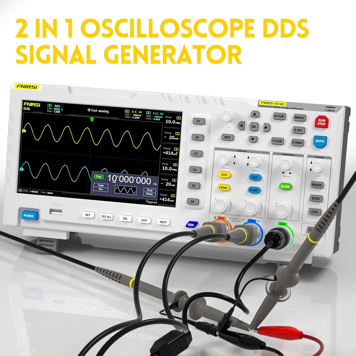
Image 4.3: Visual representation of the diverse applications for the FNIRSI 1014D, ranging from hobbyist electronics to professional diagnostics.
5. സജ്ജീകരണം
5.1 പവർ കണക്ഷൻ
- Connect the provided 5V 2A power adapter to the DC input port on the rear panel of the oscilloscope.
- അനുയോജ്യമായ പവർ ഔട്ട്ലെറ്റിലേക്ക് പവർ അഡാപ്റ്റർ പ്ലഗ് ചെയ്യുക.
- അമർത്തുക പവർ button on the front panel to turn on the device. The display will illuminate.
5.2 Probe Connection and Calibration
Before taking measurements, it is crucial to properly connect and calibrate the oscilloscope probes.
- Connect the BNC connector of the probe to the desired input channel (CH1 or CH2) on the front panel.
- Attach the ground clip of the probe to the ground reference of your circuit.
- For 10X probes, ensure the switch on the probe is set to 10X. The oscilloscope should also be configured for 10X attenuation in the channel settings.
- പ്രോബ് കാലിബ്രേഷൻ: Connect the probe tip to the calibration signal output (usually a square wave test point on the oscilloscope itself, or use the internal signal generator). Adjust the compensation trimmer on the probe until a perfect square wave is displayed on the screen.
6. പ്രവർത്തന നിർദ്ദേശങ്ങൾ
6.1 അടിസ്ഥാന ഓസിലോസ്കോപ്പ് പ്രവർത്തനങ്ങൾ
The FNIRSI 1014D features intuitive controls for waveform acquisition and display.
- യാന്ത്രിക ബട്ടൺ: അമർത്തുക ഓട്ടോ button for automatic setup of vertical, horizontal, and trigger parameters to quickly display a stable waveform.
- Vertical Controls (VOLTS/DIV): Use the vertical knobs (e.g., CH1/CH2) to adjust the vertical scale (voltage per division) and position of the waveform.
- Horizontal Controls (SEC/DIV): Use the horizontal knob to adjust the time base (time per division) and position of the waveform.
- ട്രിഗർ നിയന്ത്രണങ്ങൾ: Adjust the trigger level and mode (Single, Normal, Auto) to stabilize repetitive waveforms or capture single-shot events. The trigger edge can be set to rising or falling.
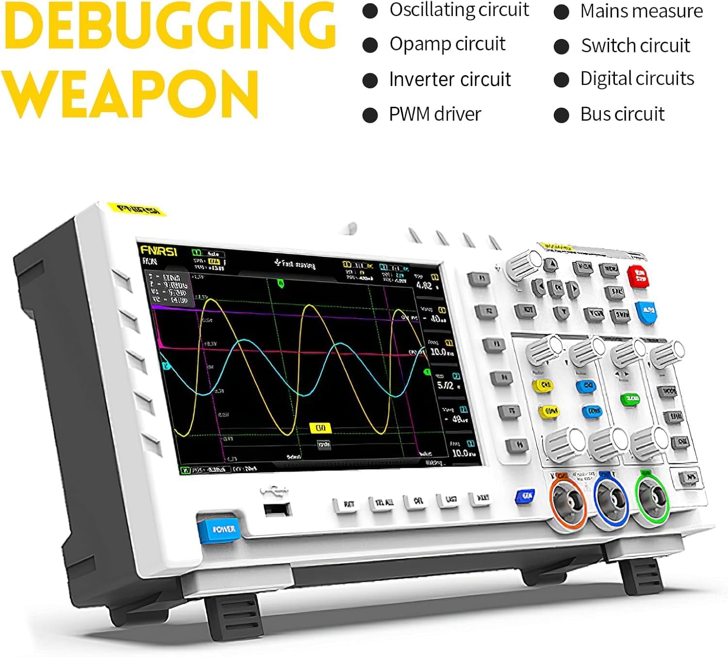
Image 6.1: The 7-inch HD screen of the FNIRSI 1014D, showing various menu options for waveform settings, measurements, and system configurations.
6.2 DDS Signal Generator Functions
The built-in DDS signal generator can produce various waveforms for testing circuits.
- Connect the signal generator output (GEN) to the circuit you wish to test.
- Access the signal generator menu (refer to the on-screen interface for specific button/menu navigation).
- Select the desired waveform type (e.g., Sine, Square, Triangle, Sawtooth).
- Adjust the frequency (in 1 Hz steps) and amplitude (fixed at 2.5 VPP) as needed.
- Customizable signals can be stored and recalled.
6.3 Measurement and Analysis Functions
- കഴ്സർ അളവ്: Activate cursor measurements to precisely determine voltage and time differences on the waveform. The device will display values directly.
- FFT (ഫാസ്റ്റ് ഫോറിയർ ട്രാൻസ്ഫോം): Use the FFT function to analyze the frequency components of a signal, useful for identifying harmonics and noise.
- Lissajous Graphics: This mode allows for the comparison of two signals' amplitude, frequency, and phase relationships, typically by displaying one signal on the X-axis and the other on the Y-axis.
6.4 Saving and Exporting Data
The FNIRSI 1014D supports saving waveforms and exporting data.
- Waveform Storage: The device can store up to 1000 waveform pictures and 1000 waveform data sets.
- യുഎസ്ബി എക്സ്പോർട്ട്: Connect a USB drive to the rear panel's USB port to export saved images or waveform data for further analysis on a computer.
7. പരിപാലനം
- വൃത്തിയാക്കൽ: ഉപകരണം വൃത്തിയാക്കാൻ മൃദുവായതും ഉണങ്ങിയതുമായ തുണി ഉപയോഗിക്കുക. കഠിനമായ അഴുക്കിന്, അല്പം ഡി.amp ഉപകരണത്തിനുള്ളിൽ ദ്രാവകം പ്രവേശിക്കുന്നില്ലെന്ന് ഉറപ്പാക്കാൻ, നേരിയ ഡിറ്റർജന്റ് ഉള്ള തുണി ഉപയോഗിക്കാം.
- സംഭരണം: Store the oscilloscope in a cool, dry place, away from direct sunlight and extreme temperatures.
- പ്രോബ് കെയർ: പ്രോബുകൾ ശ്രദ്ധാപൂർവ്വം കൈകാര്യം ചെയ്യുക. കേബിളുകൾ അമിതമായി വളയ്ക്കുകയോ സമ്മർദ്ദം ചെലുത്തുകയോ ചെയ്യുന്നത് ഒഴിവാക്കുക. പ്രോബ് നുറുങ്ങുകൾ വൃത്തിയായി സൂക്ഷിക്കുക.
8. പ്രശ്നപരിഹാരം
If you encounter issues with your FNIRSI 1014D, refer to the following common problems and solutions:
- ഒരു ഡിസ്പ്ലേയും/ഉപകരണവും ഓണാക്കുന്നില്ല:
- Ensure the power adapter is correctly connected and plugged into a working outlet.
- Verify the power button is fully pressed.
- പവർ അഡാപ്റ്ററിന് കേടുപാടുകൾ സംഭവിച്ചിട്ടുണ്ടോയെന്ന് പരിശോധിക്കുക.
- No Waveform Displayed:
- ഇൻപുട്ട് ചാനലിലേക്കും പരീക്ഷണത്തിലിരിക്കുന്ന സർക്യൂട്ടിലേക്കും പ്രോബ് ശരിയായി ബന്ധിപ്പിച്ചിട്ടുണ്ടോ എന്ന് പരിശോധിക്കുക.
- Ensure the probe's ground clip is connected to the circuit's ground.
- അമർത്തുക ഓട്ടോ button to automatically adjust settings.
- Adjust the vertical (VOLTS/DIV) and horizontal (SEC/DIV) scales.
- Check trigger settings (level, mode).
- Distorted or Unstable Waveform:
- Recalibrate the probe if using a 10X setting.
- Adjust the trigger level and mode for stability.
- Ensure the probe is properly grounded.
- Check for external noise sources.
- Signal Generator Not Outputting:
- Verify the output cable is correctly connected.
- Ensure the signal generator function is enabled and configured in the menu.
9 സ്പെസിഫിക്കേഷനുകൾ
Detailed technical specifications for the FNIRSI 1014D:
| ഫീച്ചർ | സ്പെസിഫിക്കേഷൻ |
|---|---|
| മോഡൽ | FNIRSI-1014D |
| അനലോഗ് ബാൻഡ്വിഡ്ത്ത് | 100MHz * 2 Channels |
| ചാനലുകളുടെ എണ്ണം | 2 |
| തത്സമയ എസ്ampലിംഗ് നിരക്ക് | 1GSa/s |
| ലംബ സംവേദനക്ഷമത | 50 mV/div ~ 500 V/div |
| Horizontal Time Base Range | 50S/div ~ 10nS/div |
| പരമാവധി ടെസ്റ്റ് വോളിയംtage | 40V (1X probe), 400V (10X probe) |
| സംഭരണത്തിൻ്റെ ആഴം | 240Kbit |
| ഇൻപുട്ട് പ്രതിരോധം | 1 MΩ |
| ADC Precision | 8 ബിറ്റുകൾ |
| കപ്ലിംഗ് മോഡ് | എസി/ഡിസി |
| ട്രിഗർ മോഡുകൾ | Single, Normal, Auto |
| ട്രിഗർ എഡ്ജ് | ഉയരുന്നു/വീഴുന്നു |
| ബാഹ്യ ട്രിഗർ വോളിയംtage | 0~40V |
| വിപുലീകരണ തുറമുഖങ്ങൾ | USB Image Export |
| DDS Signal Generator Output | 2.5 VPP |
| DDS Signal Frequency Steps | 1 Hz |
| DDS Signal Types | 14 types + Customizable |
| പ്രദർശിപ്പിക്കുക | 7-ഇഞ്ച് എച്ച്ഡി എൽസിഡി |
| ഡിസ്പ്ലേ റെസല്യൂഷൻ | 800 x 480 |
| മെറ്റീരിയൽ | എബിഎസ് |
| അളവുകൾ | 310mm x 145mm x 70mm |
| ഭാരം | 1.57 കി.ഗ്രാം |

Image 9.1: On-screen display of key specifications for the FNIRSI 1014D, providing a quick reference for its capabilities.
10. വാറൻ്റിയും പിന്തുണയും
FNIRSI products are designed for reliability and performance. For warranty information, technical support, or service inquiries, please refer to the contact details provided with your purchase documentation or visit the official FNIRSI webവാറന്റി ക്ലെയിമുകൾക്കുള്ള വാങ്ങലിന്റെ തെളിവായി നിങ്ങളുടെ വാങ്ങൽ രസീത് സൂക്ഷിക്കുക.