ഉൽപ്പന്നം കഴിഞ്ഞുview
This manual provides instructions for the Liftmaster Garage Door Opener Replacement Circuit Board, part number 41A5021-1E. This logic board is designed for Security+ garage door opener systems from LiftMaster, Chamberlain, Craftsman, Master Mechanic, Sears, and Wayne Dalton. It replaces various older logic board models including 41A5021-1, 41A5021-1B, 41A5021-1C, and 41A5021-1D.
This replacement board is specifically for operators without a light socket.
പ്രധാനപ്പെട്ട സുരക്ഷാ വിവരങ്ങൾ
DANGER - ACHTUNG - AVERTISSEMENT
Always disconnect power to the garage door opener before attempting any installation, repair, or maintenance. Failure to do so can result in serious injury or death.
എല്ലാ വയറിംഗും ശരിയായി ബന്ധിപ്പിച്ചിട്ടുണ്ടെന്നും സുരക്ഷിതമാണെന്നും ഉറപ്പാക്കുക.
If your original unit had a light socket, note that this replacement board does not include one. If your opener unit has a separate light, ensure the bulb does not exceed 75 watts to prevent damage.
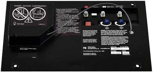
Image: Warning labels on the circuit board, indicating safety precautions such as disconnecting power before servicing and a maximum light bulb wattag75W ൻ്റെ ഇ.
അനുയോജ്യമായ മോഡലുകൾ
This replacement circuit board is compatible with the following garage door opener operator models:
- Liftmaster: 985, 1240R, 1245R, 1246R, 1255R, 1256R
- Chamberlain: 4200, 2200, 1200
- Also compatible with Security+ systems from Craftsman, Master Mechanic, Sears, and Wayne Dalton.
Replaces logic board models: 41A5021-1, 41A5021-1B, 41A5021-1C, 41A5021-1D, 41A5021-1E.
ഇൻസ്റ്റലേഷൻ നിർദ്ദേശങ്ങൾ
- പവർ വിച്ഛേദിക്കുക: Ensure the garage door opener is completely disconnected from its power source before beginning installation.
- പഴയ ബോർഡ് ആക്സസ് ചെയ്യുക: Locate and open the control panel housing of your garage door opener to access the existing circuit board.
- ലേബൽ വയറുകൾ: Carefully note or label the connections of all wires attached to the old circuit board. There are typically three bunches of wires that need to be unscrewed from the front of the board, and a ribbon cable with a rectangular connector on the back.
- പഴയ ബോർഡ് നീക്കം ചെയ്യുക: Unscrew the wires and detach the ribbon cable. Remove any screws affixing the old board to the opener chassis.
- പുതിയ ബോർഡ് ഇൻസ്റ്റാൾ ചെയ്യുക: Position the new 41A5021-1E circuit board in place. Secure it with the screws previously removed.
- വയറുകൾ വീണ്ടും ബന്ധിപ്പിക്കുക: Reconnect all wires to their corresponding terminals on the new board, ensuring a secure connection. Reattach the ribbon cable.
- പവർ പുന ore സ്ഥാപിക്കുക: Close the control panel housing and restore power to the garage door opener.
Installation typically takes 15-30 minutes. If you encounter difficulties, consult a qualified technician.
Image: The Liftmaster 41A5021-1E replacement circuit board, showing the layout of wiring terminals and adjustment screws.
വിദൂര നിയന്ത്രണ പ്രോഗ്രാമിംഗ്
After installing the new circuit board, you will need to reprogram your remote controls to the garage door opener.
- Locate the "Learn" button on your garage door opener unit. This button is usually red or purple.
- Press and immediately release the "Learn" button. The learn indicator light will glow steadily for 30 seconds.
- Within 30 seconds, press and hold the button on your remote control that you wish to operate your garage door.
- Release the remote control button when the opener lights flash or you hear two clicks. This indicates the remote has been successfully programmed.
- Repeat the process for any additional remote controls.
മെയിൻ്റനൻസ്
The circuit board itself requires minimal maintenance. However, regular inspection of your garage door opener system is recommended.
- എല്ലാ വയറിംഗ് കണക്ഷനുകളും സുരക്ഷിതമാണെന്ന് ഉറപ്പാക്കാൻ ഇടയ്ക്കിടെ പരിശോധിക്കുക.
- Keep the garage door opener unit clean and free from dust and debris.
- Consider installing surge protectors for your garage door openers to protect electronic components from power fluctuations.
ട്രബിൾഷൂട്ടിംഗ്
| പ്രശ്നം | സാധ്യമായ കാരണം | പരിഹാരം |
|---|---|---|
| Remote control not working or intermittent | Remote not programmed, weak remote battery, interference | Reprogram remote control (see "Remote Control Programming"). Replace remote battery. Check for sources of interference. |
| Garage door opener not responding | No power, wiring issue, safety sensors obstructed | Check power supply. Verify all wiring connections. Ensure safety sensors are clear and aligned. |
| Opener light stays on or does not turn off | Faulty light logic (if applicable to your specific opener model) | This replacement board does not have a light socket. If your opener has a separate light, consult your opener's specific manual. |
| Board does not fit | Incorrect model purchased | Verify compatibility with your specific garage door opener model before purchase. |
| Reduced remote range | Antenna obstruction, interference, faulty remote | Ensure the antenna wire on the opener is extended and not obstructed. Reprogram remote. Replace remote battery. |
ഉൽപ്പന്ന സവിശേഷതകൾ
- ഭാഗം നമ്പർ: 41A5021-1E
- ഇനം മോഡൽ നമ്പർ: CECOMINOD057883
- ബ്രാൻഡ്: ലിഫ്റ്റ്മാസ്റ്റർ
- നിർമ്മാതാവ്: ലിഫ്റ്റ്മാസ്റ്റർ
- പ്രവർത്തന രീതി: ഓട്ടോമാറ്റിക്
- ഇനത്തിൻ്റെ ഭാരം: ഏകദേശം 0.01 ഔൺസ്
- UPC: 753182403861
- നിറം: കറുപ്പ്
വാറൻ്റിയും ഉപഭോക്തൃ പിന്തുണയും
Specific warranty information for this replacement circuit board is not available in the provided product data. Please refer to the documentation included with your purchase or contact LiftMaster customer support directly for warranty details and technical assistance.
കൂടുതൽ സഹായത്തിന്, ഉദ്യോഗസ്ഥനെ സന്ദർശിക്കുക LiftMaster Store അല്ലെങ്കിൽ അവരുടെ ഉപഭോക്തൃ സേവന വിഭാഗവുമായി ബന്ധപ്പെടുക.