1. ആമുഖം
This manual provides detailed instructions for the installation, operation, and maintenance of the Allen-Bradley LiftMaster RETROAB 60-2728 retro-reflective photo eye. This device is designed to enhance safety by detecting obstructions in the path of automated gate operators. It operates on 12VDC and offers a maximum detection range of 30 feet. It is compatible with LiftMaster RSL12V, RSW12V, CSL24V, CSW24V, and LA500 operators.
2 സുരക്ഷാ വിവരങ്ങൾ
മുന്നറിയിപ്പ്: Failure to follow these safety instructions may result in serious injury or death, and/or damage to property.
- Always disconnect power to the gate operator before installing or servicing the photo eye.
- Installation must be performed by a qualified technician in accordance with all local electrical codes and safety standards.
- എല്ലാ വയറിംഗ് കണക്ഷനുകളും സുരക്ഷിതവും ശരിയായി ഇൻസുലേറ്റ് ചെയ്തതുമാണെന്ന് ഉറപ്പാക്കുക.
- Do not modify the photo eye or its components.
- ഇൻസ്റ്റാളേഷനും പ്രവർത്തനവും നടക്കുമ്പോൾ കുട്ടികളെയും വളർത്തുമൃഗങ്ങളെയും ഗേറ്റ് ഏരിയയിൽ നിന്ന് അകറ്റി നിർത്തുക.
- Test the photo eye's functionality regularly as described in the "Operating" section.
3. പാക്കേജ് ഉള്ളടക്കം
ഇൻസ്റ്റാളേഷൻ ആരംഭിക്കുന്നതിന് മുമ്പ് എല്ലാ ഇനങ്ങളും നിലവിലുണ്ടെന്ന് ഉറപ്പാക്കുക:
- RETROAB 60-2728 Photo Eye Sensor (1 unit)
- Mounting Bracket and Hardware (screws, nuts, washers)
- Reflector (1 unit)
- നിർദ്ദേശ മാനുവൽ (ഈ പ്രമാണം)
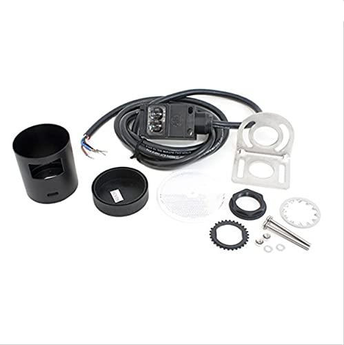
Figure 1: LiftMaster RETROAB 60-2728 Photo Eye sensor. This image shows the compact black sensor unit with its integrated cable, designed for retro-reflective operation.
4. സജ്ജീകരണവും ഇൻസ്റ്റാളേഷനും
4.1 മ ing ണ്ടിംഗ് സ്ഥാനം
The photo eye and its reflector must be mounted on opposite sides of the gate opening, ensuring an unobstructed line of sight between them. Mount both components securely to a stable surface, such as a gate post or wall, at a height that will detect typical obstructions (e.g., vehicles, people). The maximum detection range is 30 feet (9.1 meters).
4.2 Mounting the Sensor and Reflector
- Using the provided mounting bracket and hardware, securely attach the photo eye sensor to one side of the gate opening.
- Attach the reflector to the opposite side of the gate opening. Ensure the reflector is positioned directly in line with the sensor.
- The sensor and reflector should be mounted at the same height and parallel to each other for optimal performance.

ചിത്രം 2: വിശദമായി view of the LiftMaster RETROAB 60-2728 Photo Eye. This image highlights the lens and housing of the sensor, showing its robust construction.
5. വയറിംഗ് നിർദ്ദേശങ്ങൾ
പ്രധാനപ്പെട്ടത്: Ensure power to the gate operator is disconnected before performing any wiring.
The RETROAB 60-2728 photo eye operates on 12VDC. Refer to your specific gate operator's manual for exact wiring terminal locations. Typically, the photo eye will connect to the operator's safety input terminals.
- ബന്ധിപ്പിക്കുക പോസിറ്റീവ് (+) wire from the photo eye to the 12VDC (+) terminal on the gate operator control board.
- ബന്ധിപ്പിക്കുക നെഗറ്റീവ് (-) wire from the photo eye to the Common (-) terminal on the gate operator control board.
- ബന്ധിപ്പിക്കുക സിഗ്നൽ wire from the photo eye to the designated സുരക്ഷാ ഇൻപുട്ട് terminal on the gate operator control board.
This photo eye is compatible with LiftMaster RSL12V, RSW12V, CSL24V, CSW24V, and LA500 operators. Consult the operator's manual for specific wiring diagrams.
6. പ്രവർത്തന നിർദ്ദേശങ്ങൾ
The RETROAB 60-2728 is a retro-reflective photo eye. This means the sensor unit emits an infrared beam that travels to a reflector and bounces back to the sensor. When an object breaks this beam, the sensor detects the interruption and signals the gate operator to stop or reverse, preventing potential impact.
6.1 Alignment Indicator
The photo eye typically features an LED indicator. When the sensor is properly aligned with the reflector and the beam is unobstructed, this LED will illuminate (e.g., solid green). If the beam is broken or misaligned, the LED will change state (e.g., turn off or flash), indicating an issue.
6.2 ഫങ്ഷണൽ ടെസ്റ്റ്
After installation and wiring, perform the following test:
- ഗേറ്റ് ഓപ്പറേറ്ററിലേക്ക് പവർ പ്രയോഗിക്കുക.
- Observe the photo eye's alignment indicator LED. It should be illuminated, indicating proper alignment.
- Initiate a gate closing cycle.
- While the gate is closing, carefully place an object (e.g., a cardboard box) in the path of the photo eye beam.
- The gate should immediately stop or reverse its direction. If it does not, disconnect power and refer to the "Troubleshooting" section.
- Remove the object and allow the gate to complete its cycle.
Repeat this test periodically to ensure continued safe operation.
7. പരിപാലനം
Regular maintenance ensures the longevity and reliable operation of your photo eye.
- വൃത്തിയാക്കൽ: Periodically clean the lens of the photo eye sensor and the surface of the reflector with a soft, damp cloth. Dust, dirt, spiderwebs, or debris can obstruct the beam and cause false detections or prevent proper operation.
- പരിശോധന: Visually inspect the sensor, reflector, and wiring for any signs of damage, corrosion, or loose connections. Ensure mounting hardware remains secure.
- പ്രവർത്തനക്ഷമത പരിശോധന: Perform the functional test described in Section 6.2 at least once a month, or more frequently in harsh environments.
8. പ്രശ്നപരിഹാരം
If the photo eye is not functioning correctly, refer to the following common issues and solutions:
| പ്രശ്നം | സാധ്യമായ കാരണം | പരിഹാരം |
|---|---|---|
| Gate does not close, or reverses immediately. | Beam obstructed or misaligned. | Check for obstructions. Clean sensor lens and reflector. Re-align sensor and reflector until alignment LED is solid. |
| Photo eye LED is off. | No power to the photo eye or faulty wiring. | Verify 12VDC power supply. Check all wiring connections for security and correct polarity. |
| Gate closes even with an obstruction. | Photo eye not wired correctly to operator, or photo eye is faulty. | Review wiring instructions (Section 5) and your gate operator's manual. Perform functional test (Section 6.2). If problem persists, the photo eye may need replacement. |
| ഇടയ്ക്കിടെയുള്ള പ്രവർത്തനം. | Loose wiring, environmental interference, or partial obstruction. | Check all wiring. Ensure sensor and reflector are clean. Verify stable mounting. Consider potential sources of interference (e.g., direct sunlight, reflective surfaces). |
9 സ്പെസിഫിക്കേഷനുകൾ
- മോഡൽ: RETROAB 60-2728
- തരം: Retro-reflective Photo Eye
- വൈദ്യുതി ആവശ്യകത: 12VDC
- പരമാവധി കണ്ടെത്തൽ പരിധി: 30 അടി (9.1 മീറ്റർ)
- അനുയോജ്യത: LiftMaster RSL12V, RSW12V, CSL24V, CSW24V, LA500 operators
- ഭാഗം നമ്പർ: 60-2728
- ASIN: B00DP41BWY
10. വാറൻ്റിയും പിന്തുണയും
For warranty information, please refer to the documentation provided with your purchase or contact the original seller or manufacturer directly. Warranty terms and conditions may vary.
For technical support, please contact your authorized Allen-Bradley or LiftMaster dealer or the point of purchase. Ensure you have your model number (60-2728) and purchase details available when seeking support.


