1. ആമുഖം
The STLINK-V3SET is a modular, stand-alone debugging and programming probe designed for use with STM8 and STM32 microcontrollers. This device consists of a main module and a complementary adapter board, providing comprehensive functionality for development and testing.
It facilitates communication with target microcontrollers via SWIM and JTAG/SWD interfaces. Additionally, the STLINK-V3SET offers a Virtual COM port for host PC communication through UART, and bridge interfaces (SPI, I2C, CAN, GPIOs) for programming via bootloader. Its modular design allows for feature expansion through additional modules, such as the adapter board.
2 പ്രധാന സവിശേഷതകൾ
- മോഡുലാർ ഡിസൈൻ: Stand-alone probe with support for modular extensions.
- വൈദ്യുതി വിതരണം: Self-powered via a USB connector (Micro-B).
- USB ഇൻ്റർഫേസ്: USB 2.0 high-speed compatible.
- ഫേംവെയർ അപ്ഡേറ്റ്: Direct firmware update (DFU) support.
- JTAG / SWD Debugging:
- Application voltage support: 3 V to 3.6 V.
- 5 V tolerant inputs.
- Flat cables: STDC14 to MIPI10 / STDC14 / MIPI20 (1.27 mm pitch connectors).
- JTAG communication support.
- SWD and Serial Wire Viewer (SWV) communication support.
- SWIM Features (with adapter board MB1440):
- Application voltage support: 1.65 V to 5.5 V.
- SWIM header (2.54 mm pitch).
- SWIM low-speed and high-speed modes support.
- Virtual COM Port (VCP):
- Application voltage support on UART: 3 V to 3.6 V.
- 5 V tolerant inputs.
- VCP frequency up to 15 MHz.
- Available on STDC14 debug connector (not on MIPI10).
- Multi-path Bridge (USB to SPI/UART/I2C/CAN/GPIOs):
- Application voltage support: 3 V to 3.6 V.
- 5 V tolerant inputs.
- Signals available on adapter board only (MB1440).
- Flash Programming: Drag-and-drop functionality.
- LED സൂചകങ്ങൾ: Two color LEDs for communication and power status.
3. സജ്ജീകരണ നിർദ്ദേശങ്ങൾ
3.1. അൺബോക്സിംഗും ഘടക തിരിച്ചറിയലും
പാക്കേജ് തുറക്കുമ്പോൾ, എല്ലാ ഘടകങ്ങളും ഉണ്ടെന്ന് ഉറപ്പാക്കുക:
- STLINK-V3SET Main Module
- Adapter Board (MB1440)
- USB Cable (Micro-B)
- Flat cables (STDC14 to MIPI10 / STDC14 / MIPI20)
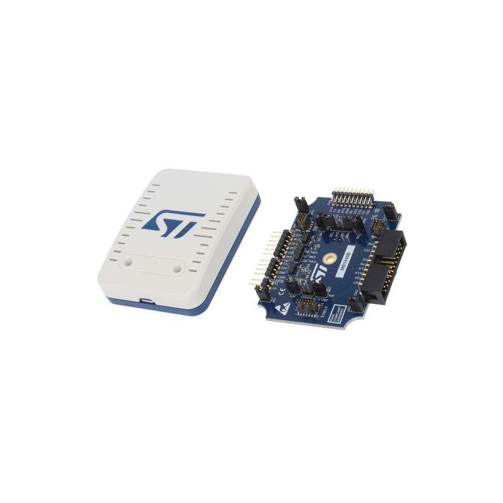
ചിത്രം 1: STLINK-V3SET Main Module (left) and Adapter Board (right). The main module is a white and blue rectangular device, while the adapter board is a blue circuit board with various connectors and components.
3.2. ഡ്രൈവർ ഇൻസ്റ്റാളേഷൻ
Before connecting the STLINK-V3SET to your computer, ensure that the necessary drivers are installed. These drivers are typically available on the official STMicroelectronics website. Download and install the latest ST-LINK drivers for your operating system.
3.3. ഉപകരണം ബന്ധിപ്പിക്കുന്നു
- Connect the STLINK-V3SET Main Module to your computer using the provided USB Micro-B cable. The device is self-powered via USB.
- If using the adapter board (MB1440) for SWIM or bridge interfaces, connect it to the main module as required.
- Connect the appropriate debug cable (e.g., STDC14, MIPI10, MIPI20) from the STLINK-V3SET to your target STM8 or STM32 application board. Ensure correct pin orientation.
- Verify that the power and communication LEDs on the STLINK-V3SET illuminate, indicating proper connection and power.
4. പ്രവർത്തന നിർദ്ദേശങ്ങൾ
4.1. Debugging STM32 Microcontrollers (JTAG/എസ്ഡബ്ല്യുഡി)
- Ensure your development environment (e.g., STM32CubeIDE, Keil MDK, IAR Embedded Workbench) is configured to use ST-LINK/V3 as the debugger.
- Connect the STLINK-V3SET to your STM32 target board using a JTAG or SWD cable.
- In your IDE, initiate a debug session. The STLINK-V3SET will establish communication with the target microcontroller.
- You can now step through code, set breakpoints, inspect variables, and perform other debugging operations.
4.2. Programming STM8 Microcontrollers (SWIM)
For STM8 programming, the adapter board (MB1440) is required.
- Connect the adapter board (MB1440) to the STLINK-V3SET Main Module.
- Connect the SWIM header from the adapter board to your STM8 target board.
- Use the appropriate programming software (e.g., STVP) to load your firmware onto the STM8 microcontroller.
4.3. Virtual COM Port (VCP) Usage
The VCP feature allows your host PC to communicate with the target microcontroller via UART.
- Ensure the STLINK-V3SET is connected to the target via the STDC14 debug connector.
- On your PC, identify the assigned COM port for the STLINK-V3SET VCP.
- Use a terminal emulator program (e.g., PuTTY, Tera Term) to open a connection to this COM port with the correct baud rate and settings.
- Data sent from your PC will be relayed to the target microcontroller's UART, and vice-versa.
4.4. Multi-path Bridge Interfaces (SPI, I2C, CAN, GPIOs)
These interfaces are available on the adapter board (MB1440) and allow for direct communication with peripherals on your target board.
- Connect the adapter board (MB1440) to the STLINK-V3SET Main Module.
- Wire the specific SPI, I2C, CAN, or GPIO pins from the adapter board to your target device.
- Utilize the ST-LINK utility software or custom applications to interact with these bridge interfaces.
4.5. Drag-and-Drop Flash Programming
The STLINK-V3SET supports convenient drag-and-drop programming for compatible microcontrollers.
- Connect the STLINK-V3SET to your target board.
- The target microcontroller may appear as a removable drive on your computer.
- Drag and drop your compiled firmware file (e.g., .hex, .bin) onto this drive to program the microcontroller.
5. പരിപാലനം
5.1. വൃത്തിയാക്കൽ
Keep the STLINK-V3SET and its adapter board clean and free from dust. Use a soft, dry cloth for cleaning. Avoid using liquid cleaners or solvents, as these can damage the electronic components.
5.2. ഫേംവെയർ അപ്ഡേറ്റുകൾ
എസ്ടിമൈക്രോഇലക്ട്രോണിക്സ് പതിവായി പരിശോധിക്കുക. website for firmware updates for your STLINK-V3SET. Firmware updates can provide new features, performance improvements, and bug fixes. Use the official ST-LINK utility software to perform firmware updates.
Procedure for Firmware Update:
- Download the latest ST-LINK utility from the STMicroelectronics webസൈറ്റ്.
- Connect the STLINK-V3SET to your computer via USB.
- Launch the ST-LINK utility.
- Navigate to the firmware update section within the utility and follow the on-screen instructions to update the device firmware.
6. പ്രശ്നപരിഹാരം
| പ്രശ്നം | സാധ്യമായ കാരണം | പരിഹാരം |
|---|---|---|
| ഉപകരണം പിസി തിരിച്ചറിഞ്ഞില്ല |
|
|
| Cannot connect to target microcontroller |
|
|
| ഫേംവെയർ അപ്ഡേറ്റ് പരാജയപ്പെട്ടു |
|
|
7 സ്പെസിഫിക്കേഷനുകൾ
| ഫീച്ചർ | വിശദാംശങ്ങൾ |
|---|---|
| മോഡലിൻ്റെ പേര് | STLINK-V3SET |
| ബ്രാൻഡ് | എസ്ടിമൈക്രോ ഇലക്ട്രോണിക്സ് |
| കണക്റ്റിവിറ്റി ടെക്നോളജി | ഐ2സി, യുഎസ്ബി |
| ഉൾപ്പെടുത്തിയ ഘടകങ്ങൾ | Main module, Adapter board (MB1440) |
| ഉൽപ്പന്ന അളവുകൾ | 4 x 3 x 1 ഇഞ്ച് |
| ഭാരം | 4 ഔൺസ് |
| JTAG/SWD ആപ്ലിക്കേഷൻ വോളിയംtage | 3 V മുതൽ 3.6 V വരെ (5 V ടോളറന്റ് ഇൻപുട്ടുകൾ) |
| SWIM ആപ്ലിക്കേഷൻ വോളിയംtage | 1.65 V to 5.5 V (with adapter board MB1440) |
| VCP Application Voltage | 3 V മുതൽ 3.6 V വരെ (5 V ടോളറന്റ് ഇൻപുട്ടുകൾ) |
| VCP Frequency | 15 MHz വരെ |
| യുഎസ്ബി ഇൻ്റർഫേസ് | USB 2.0 high-speed (Micro-B connector) |
8. വാറൻ്റി വിവരങ്ങൾ
For detailed warranty information regarding the STLINK-V3SET, please refer to the official STMicroelectronics website or the documentation included with your purchase. Warranty terms typically cover manufacturing defects for a specified period from the date of purchase.
Protection plans may be available from third-party providers. For example, 2-Year and 3-Year Protection Plans are offered, as well as a Complete Protect plan. These are separate from the manufacturer's warranty.
9. സാങ്കേതിക പിന്തുണ
For technical assistance, documentation, software downloads, and community forums, please visit the official STMicroelectronics support website. You can find resources related to the STLINK-V3SET, STM8, and STM32 microcontrollers.
STMicroelectronics Official Webസൈറ്റ്: www.st.com


