WAGO 286-364 Switching Relay Module User Manual
മോഡൽ: 286-364
1. ഉൽപ്പന്നം കഴിഞ്ഞുview
The WAGO 286-364 Switching Relay Module is designed for industrial electrical applications, converting a 24VDC input signal to control a 250VAC, 5AMP output. This module is a critical component for various control systems, offering reliable switching capabilities.
പ്രധാന സവിശേഷതകളിൽ ഇവ ഉൾപ്പെടുന്നു:
- ഇൻപുട്ട് വോളിയംtage: 24VDC
- Putട്ട്പുട്ട് വോളിയംtage: 250VAC
- ഔട്ട്പുട്ട് കറൻ്റ്: 5AMP
- Function: Switching Relay Module
- Category: Panel Accessories, Relay/Socket

ചിത്രം 1: ഓവർview of three WAGO 286-364 Switching Relay Modules, showcasing their compact design and grey housing.
2. സജ്ജീകരണവും ഇൻസ്റ്റാളേഷനും
Proper installation is crucial for the safe and effective operation of the WAGO 286-364 module. Ensure all power sources are disconnected before beginning installation.
2.1. മൗണ്ടിംഗ്
The module is designed for panel mounting. Secure it firmly using appropriate fasteners or DIN rail clips if applicable to your specific model variant. Ensure adequate ventilation around the module to prevent overheating.
2.2. വയറിംഗ് കണക്ഷനുകൾ
Refer to the terminal markings on the module for correct wiring. The module typically features input terminals for 24VDC control signals and output terminals for the 250VAC load.
- ബന്ധിപ്പിക്കുക 24VDC control signal to the designated input terminals (e.g., R1+, R2-).
- ബന്ധിപ്പിക്കുക 250VAC load to the output terminals (e.g., 13, 14).
- ഷോർട്ട് സർക്യൂട്ടുകൾ തടയുന്നതിന് എല്ലാ കണക്ഷനുകളും സുരക്ഷിതമാണെന്നും ശരിയായി ഇൻസുലേറ്റ് ചെയ്തിട്ടുണ്ടെന്നും ഉറപ്പാക്കുക.

ചിത്രം 2: വിശദമായി view of the module's connection pins, highlighting the robust design for secure wiring.

ചിത്രം 3: മുകളിൽ view of the modules, indicating the 'TEST' points and model number for identification and testing purposes.
3. പ്രവർത്തന നിർദ്ദേശങ്ങൾ
Once properly installed and wired, the WAGO 286-364 module operates by receiving a 24VDC signal to switch the 250VAC output. The module acts as an interface between low-voltage control circuits and higher-voltagഇ ലോഡ്സ്.
- എപ്പോൾ എ 24VDC signal is applied to the input terminals, the internal relay will energize.
- Upon energization, the output contacts will switch, allowing the 250VAC current to flow to the connected load.
- When the 24VDC input signal is removed, the relay will de-energize, opening the output contacts and disconnecting the 250VAC load.
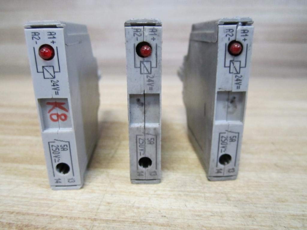
ചിത്രം 4: വശം view of the modules, showing the indicator LED which illuminates when the relay is energized, and clearly marked input/output terminals.
3.1. ഇൻഡിക്കേറ്റർ LED
The module is equipped with an indicator LED (visible in Figure 4) that provides visual feedback on the relay's status. The LED illuminates when the 24VDC input signal is present and the relay is energized, confirming proper operation.
4. പരിപാലനം
The WAGO 286-364 Switching Relay Module is designed for long-term, maintenance-free operation under normal industrial conditions. However, periodic inspection is recommended to ensure optimal performance and safety.
- വിഷ്വൽ പരിശോധന: Regularly check the module for any signs of physical damage, discoloration, or loose connections.
- വൃത്തിയാക്കൽ: If necessary, gently clean the exterior of the module with a dry, soft cloth. Do not use abrasive cleaners or solvents.
- കണക്ഷൻ സമഗ്രത: Periodically verify that all wiring connections are secure and free from corrosion.
Always disconnect power to the module and associated circuits before performing any maintenance or inspection.
5. പ്രശ്നപരിഹാരം
If the WAGO 286-364 module is not functioning as expected, consider the following troubleshooting steps:
- Module Not Switching:
- എന്ന് പരിശോധിക്കുക 24VDC input signal is present and correctly wired to the input terminals.
- Check if the indicator LED on the module is illuminated when the input signal is applied. If not, there may be an issue with the input signal or the module itself.
- ഔട്ട്പുട്ട് പവർ ഇല്ല:
- ഉറപ്പാക്കുക 250VAC power source for the load is active and correctly wired to the output terminals.
- Confirm that the load itself is functional and not drawing excessive current that could damage the module or trip protective devices.
- അമിത ചൂടാക്കൽ:
- Check for proper ventilation around the module.
- Ensure the load current does not exceed the module's 5AMP റേറ്റിംഗ്.
If issues persist after following these steps, contact a qualified electrician or WAGO technical support.
6 സ്പെസിഫിക്കേഷനുകൾ
| ആട്രിബ്യൂട്ട് | മൂല്യം |
|---|---|
| മോഡൽ നമ്പർ | 286-364 |
| ഇൻപുട്ട് വോളിയംtage | 24VDC |
| Putട്ട്പുട്ട് വോളിയംtage | 250VAC |
| ഔട്ട്പുട്ട് നിലവിലെ റേറ്റിംഗ് | 5 Amps |
| നിർമ്മാതാവ് | വാഗോ |
| ASIN | B07M93Z7W7 |
| ആദ്യം ലഭ്യമായ തീയതി | ഡിസംബർ 20, 2018 |
7. വാറൻ്റിയും പിന്തുണയും
Specific warranty details for the WAGO 286-364 Switching Relay Module are typically provided at the point of purchase or through official WAGO documentation. Please refer to your purchase invoice or the manufacturer's webഏറ്റവും പുതിയ വാറന്റി വിവരങ്ങൾക്ക് സൈറ്റ്.
For technical support, product inquiries, or assistance with troubleshooting beyond the scope of this manual, please contact WAGO directly through their official channels. Contact information can usually be found on the WAGO webസൈറ്റ് അല്ലെങ്കിൽ ഉൽപ്പന്ന പാക്കേജിംഗ്.


