1. ആമുഖം
The ANENG AN8009 is a compact, auto/manual ranging True-RMS digital multimeter designed for accurate measurement of various electrical parameters. It is suitable for use in automotive maintenance, electrical engineering, and educational laboratories. This manual provides detailed instructions for the safe and effective operation, setup, and maintenance of your AN8009 multimeter.
2 സുരക്ഷാ വിവരങ്ങൾ
To ensure safe operation and service of the meter, please read all instructions carefully before use. Failure to observe safety warnings can result in electric shock, fire, or damage to the meter.
- Always disconnect test leads from the circuit before changing functions.
- റേറ്റുചെയ്ത വോള്യത്തേക്കാൾ കൂടുതൽ പ്രയോഗിക്കരുത്tage, മീറ്ററിൽ അടയാളപ്പെടുത്തിയിരിക്കുന്നതുപോലെ, ടെർമിനലുകൾക്കിടയിൽ അല്ലെങ്കിൽ ഏതെങ്കിലും ടെർമിനലിനും ഭൂമിക്കും ഇടയിൽ.
- വോള്യവുമായി പ്രവർത്തിക്കുമ്പോൾ അതീവ ജാഗ്രത പാലിക്കുകtages above 30V AC RMS, 42V peak, or 60V DC. Such voltagഒരു ഷോക്ക് അപകടമാണ്.
- Keep your fingers behind the probe barriers during measurements.
- മീറ്റർ കേടായതായി തോന്നുകയോ ടെസ്റ്റ് ലീഡുകളിലെ ഇൻസുലേഷൻ തകരാറിലാവുകയോ ചെയ്താൽ അത് ഉപയോഗിക്കരുത്.
- Ensure the battery cover is securely closed before operating the meter.
- കൃത്യമായ റീഡിംഗുകൾ ഉറപ്പാക്കാൻ കുറഞ്ഞ ബാറ്ററി സൂചകം ദൃശ്യമാകുമ്പോൾ ഉടൻ ബാറ്ററികൾ മാറ്റിസ്ഥാപിക്കുക.
3. ഉൽപ്പന്നം കഴിഞ്ഞുview
The ANENG AN8009 multimeter features a large, backlit LCD display for clear readings in various lighting conditions. It includes a rotary function switch, input jacks, and various buttons for mode selection and data hold.
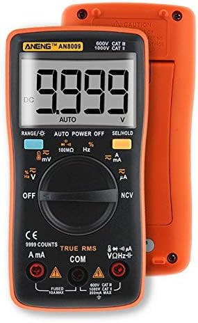
ചിത്രം 3.1: മുൻഭാഗം View of ANENG AN8009 Digital Multimeter. This image displays the multimeter's front panel, showing the large digital display, rotary function switch, input jacks (VΩHz, COM, A, mA), and various function buttons. The orange casing is visible around the black main body.
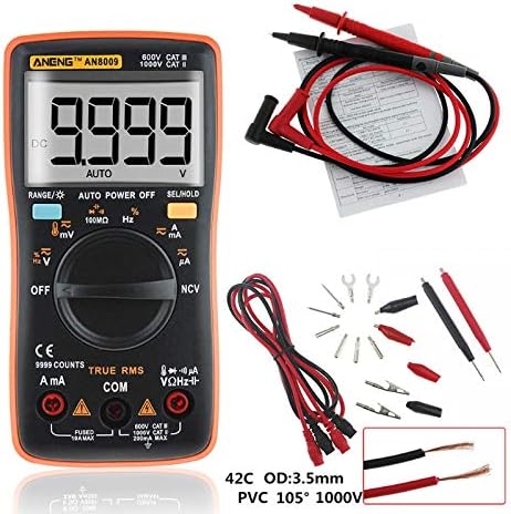
Figure 3.2: ANENG AN8009 Digital Multimeter with Test Leads and Accessories. This image shows the ANENG AN8009 multimeter alongside its standard accessories, including red and black test leads, alligator clips, and various probe tips. A user manual is also visible in the background.
3.1 പ്രധാന ഘടകങ്ങൾ
- LCD ഡിസ്പ്ലേ: അളക്കൽ റീഡിംഗുകൾ, യൂണിറ്റുകൾ, പ്രവർത്തന സൂചകങ്ങൾ എന്നിവ കാണിക്കുന്നു.
- ഫംഗ്ഷൻ സ്വിച്ച്: Rotary dial to select measurement modes (Voltage, കറന്റ്, റെസിസ്റ്റൻസ് മുതലായവ).
- ഇൻപുട്ട് ജാക്കുകൾ: Terminals for connecting test leads (VΩHz, COM, A, mA).
- ബട്ടണുകൾ: For features like RANGE, AUTO POWER OFF, SEL/HOLD, and backlight activation.
4. സജ്ജീകരണം
4.1 ബാറ്ററി ഇൻസ്റ്റാളേഷൻ
The ANENG AN8009 requires two 1.5V AAA batteries (not included) for operation.
- മൾട്ടിമീറ്റർ ഓഫ് ചെയ്തിട്ടുണ്ടെന്ന് ഉറപ്പാക്കുക.
- മീറ്ററിന്റെ പിൻഭാഗത്ത് ബാറ്ററി കമ്പാർട്ട്മെന്റ് കണ്ടെത്തുക.
- ബാറ്ററി കമ്പാർട്ട്മെന്റ് കവർ തുറക്കാൻ ഒരു സ്ക്രൂഡ്രൈവർ ഉപയോഗിക്കുക.
- Insert two 1.5V AAA batteries, observing the correct polarity (+ and -).
- ബാറ്ററി കമ്പാർട്ട്മെന്റ് കവർ മാറ്റി സ്ക്രൂ ഉപയോഗിച്ച് സുരക്ഷിതമാക്കുക.
4.2 ടെസ്റ്റ് ലീഡുകൾ ബന്ധിപ്പിക്കുന്നു
Always connect the black test lead to the COM (common) jack. Connect the red test lead to the appropriate input jack based on the desired measurement:
- VΩHz: വോളിയത്തിന്tage, പ്രതിരോധം, ആവൃത്തി, കപ്പാസിറ്റൻസ്, ഡയോഡ്, തുടർച്ച അളവുകൾ.
- mA: For current measurements up to 600mA.
- A: For current measurements up to 10A.
5. പ്രവർത്തന നിർദ്ദേശങ്ങൾ
Turn the rotary switch to the desired function. The meter typically defaults to auto-ranging. Press the 'SEL' button to switch between functions within a single rotary switch position (e.g., AC/DC voltage, diode/continuity).
5.1 DC/AC വോളിയംtage Measurement (V, mV)
- Connect the black lead to COM and the red lead to VΩHz.
- Turn the rotary switch to the V (Voltage) position. The meter will typically default to DCV. Press 'SEL' to switch to ACV if needed.
- Connect the test probes in parallel to the circuit or component under test.
- വാല്യം വായിക്കുകtagഡിസ്പ്ലേയിലെ ഇ മൂല്യം.
5.2 DC/AC Current Measurement (A, mA, uA)
ജാഗ്രത: Never connect the meter in parallel to a voltage source when measuring current. This can blow the fuse or damage the meter. Always connect in series with the load.
- Connect the black lead to COM. Connect the red lead to mA for currents up to 600mA, or to A for currents up to 10A.
- Turn the rotary switch to the A (Current) position. Press 'SEL' to switch between DC/AC current or different ranges (uA, mA, A) if necessary.
- Open the circuit where current is to be measured and connect the meter in series.
- ഡിസ്പ്ലേയിലെ നിലവിലെ മൂല്യം വായിക്കുക.
5.3 പ്രതിരോധ അളവ് (Ω)
- Connect the black lead to COM and the red lead to VΩHz.
- Turn the rotary switch to the Ω (Resistance) position.
- Ensure the circuit is de-energized before measuring resistance. Connect the test probes across the component.
- ഡിസ്പ്ലേയിലെ പ്രതിരോധ മൂല്യം വായിക്കുക.
5.4 Capacitance Measurement (nF, uF, mF)
- Connect the black lead to COM and the red lead to VΩHz.
- Turn the rotary switch to the Capacitance position.
- Discharge the capacitor completely before measurement. Connect the test probes across the capacitor terminals.
- ഡിസ്പ്ലേയിലെ കപ്പാസിറ്റൻസ് മൂല്യം വായിക്കുക.
5.5 Frequency Measurement (Hz, KHz, MHz)
- Connect the black lead to COM and the red lead to VΩHz.
- Turn the rotary switch to the Hz (Frequency) position.
- Connect the test probes in parallel to the signal source.
- ഡിസ്പ്ലേയിലെ ഫ്രീക്വൻസി മൂല്യം വായിക്കുക.
5.6 ഡയോഡ് ടെസ്റ്റ്
- Connect the black lead to COM and the red lead to VΩHz.
- Turn the rotary switch to the Diode/Continuity position. Press 'SEL' until the diode symbol appears.
- ചുവന്ന പ്രോബ് ഡയോഡിന്റെ ആനോഡിലേക്കും കറുത്ത പ്രോബ് കാഥോഡിലേക്കും ബന്ധിപ്പിക്കുക.
- ഒരു മുൻ വാല്യംtage drop will be displayed for a good diode. Reverse the probes; the display should show 'OL' (open loop).
5.7 തുടർച്ച പരിശോധന
- Connect the black lead to COM and the red lead to VΩHz.
- Turn the rotary switch to the Diode/Continuity position. Press 'SEL' until the continuity symbol appears.
- സർക്യൂട്ടിലോ ഘടകത്തിലോ ഉടനീളം ടെസ്റ്റ് പ്രോബുകൾ ബന്ധിപ്പിക്കുക.
- If continuity exists (resistance below approximately 50Ω), the buzzer will sound.
5.8 താപനില അളക്കൽ
- Connect the temperature probe (K-type thermocouple) to the VΩHz and COM jacks, observing polarity.
- Turn the rotary switch to the Temp position.
- താപനില അളക്കേണ്ട വസ്തുവിന് മുകളിലോ അതിനടുത്തോ പ്രോബ് ടിപ്പ് വയ്ക്കുക.
- Read the temperature value on the display (in °C or °F).
5.9 നോൺ-കോൺടാക്റ്റ് വോളിയംtagഇ (NCV) കണ്ടെത്തൽ
- റോട്ടറി സ്വിച്ച് NCV സ്ഥാനത്തേക്ക് തിരിക്കുക.
- Move the top end of the meter close to the conductor being tested.
- എസി വോള്യം ആണെങ്കിൽtage is detected, the meter will emit an audible beep and the NCV indicator will light up.
5.10 ഡാറ്റ ഹോൾഡ് പ്രവർത്തനം
ഡിസ്പ്ലേയിലെ നിലവിലെ റീഡിംഗ് ഫ്രീസ് ചെയ്യാൻ 'ഹോൾഡ്' ബട്ടൺ അമർത്തുക. ഹോൾഡ് ഫംഗ്ഷൻ റിലീസ് ചെയ്യാൻ അത് വീണ്ടും അമർത്തുക.
5.11 ബാക്ക്ലൈറ്റ്
Press the backlight button (often combined with 'HOLD' or 'SEL') to turn the display backlight on or off. The backlight typically turns off automatically after a short period to conserve battery life.
6. പരിപാലനം
6.1 വൃത്തിയാക്കൽ
പരസ്യം ഉപയോഗിച്ച് കേസ് തുടയ്ക്കുകamp തുണിയും നേരിയ ഡിറ്റർജന്റും. അബ്രാസീവ്സുകളോ ലായകങ്ങളോ ഉപയോഗിക്കരുത്. ഇൻപുട്ട് ടെർമിനലുകൾ അഴുക്കും ഈർപ്പവും ഇല്ലാതെ സൂക്ഷിക്കുക.
6.2 ബാറ്ററി മാറ്റിസ്ഥാപിക്കൽ
When the low battery indicator appears on the display, replace the batteries as described in Section 4.1. Using the meter with a low battery can lead to inaccurate readings.
6.3 ഫ്യൂസ് മാറ്റിസ്ഥാപിക്കൽ
If the current measurement function fails, the fuse may need replacement. The AN8009 typically uses two fuses: a 200mA/250V fast-blow fuse for the mA input and a 10A/250V fast-blow fuse for the A input. Refer to the markings on the meter for exact fuse specifications. Fuse replacement should only be performed by qualified personnel.
- Ensure the meter is powered off and test leads are disconnected.
- Open the battery compartment and then the main casing screws (if applicable, consult the meter's physical design).
- Carefully remove the old fuse and replace it with a new fuse of the identical type and rating.
- Reassemble the meter, ensuring all screws are tightened.
6.4 സംഭരണം
If the meter is not to be used for an extended period, remove the batteries to prevent leakage and damage. Store the meter in a cool, dry place, away from direct sunlight and extreme temperatures.
7. പ്രശ്നപരിഹാരം
- ഡിസ്പ്ലേ ഇല്ല അല്ലെങ്കിൽ മങ്ങിയ ഡിസ്പ്ലേ: Check battery installation and charge. Replace batteries if necessary.
- 'OL' (ഓവർലോഡ്) പ്രദർശിപ്പിച്ചിരിക്കുന്നു: The input value exceeds the selected range or the maximum measurement capability of the meter. Select a higher range or ensure the input is within specifications.
- തെറ്റായ വായനകൾ: Check battery level, ensure test leads are properly connected, and verify the correct function is selected. Clean input jacks if dirty.
- Current measurement not working: Check the fuse for the respective current input (mA or A). Replace if blown.
8 സ്പെസിഫിക്കേഷനുകൾ
| പരാമീറ്റർ | സ്പെസിഫിക്കേഷൻ |
|---|---|
| പ്രവർത്തന താപനില | 0 - 40 ഡിഗ്രി സെൽഷ്യസ് |
| പ്രവർത്തന ഹ്യുമിഡിറ്റി | 75% RH |
| സ്റ്റോറേജ് അവസ്ഥ | -20 ~ 60 °C |
| സംഭരണ ഈർപ്പം | 80% RH |
| ഓപ്പറേറ്റിംഗ് മോഡ് | ഓട്ടോ/മാനുവൽ റേഞ്ചിംഗ് |
| താപനില പരിധി അളക്കുന്നു | -20 ~ 1000 °C / -4 ~ 1832 °F |
| കപ്പാസിറ്റൻസ് ശ്രേണി അളക്കൽ | 9.99nF / 99.99nF / 999.9nF / 9.99uF / 99.99uF / 999.9uF / 9.999mF |
| വോളിയം അളക്കുന്നുtage Range (DC/AC) | 999.9mV / 9.999V / 99.99V / 999.9V (DC) / 750V (AC) |
| Measuring Current Range (DC/AC) | 99.99uA / 999.9uA / 999.9mA / 9.999A |
| പ്രതിരോധ ശ്രേണി അളക്കൽ | 99.99Ω / 999.9Ω / 9.999kΩ / 99.99kΩ / 999.9kΩ / 99.99MΩ |
| ഫ്രീക്വൻസി റേഞ്ച് | 99.99Hz / 999.9Hz / 9.999KHz / 99.99KHz / 999.9KHz / 9.999MHz |
| സ്ക്വയർ വേവ് ഔട്ട്പുട്ട് | 50Hz - 1000Hz (various steps) |
| ഡിസ്പ്ലേ തരം | ഡിജിറ്റൽ ഡിസ്പ്ലേ (9999 എണ്ണം) |
| ഡയോഡ് ടെസ്റ്റ് | അതെ |
| തുടർച്ച | അതെ |
| ഡ്യൂട്ടി സൈക്കിൾ | 1% - 99% |
| Sample നിരക്ക് | സെക്കൻഡിൽ 3 തവണ |
| ശക്തി | 2 * 1.5V AAA batteries |
9. വാറൻ്റിയും പിന്തുണയും
For warranty information and technical support, please refer to the documentation provided with your purchase or contact the seller/manufacturer directly. Keep your purchase receipt as proof of purchase.


