1. ആമുഖം
This manual provides essential instructions for the safe and effective operation of your AOPUTTRIVER AP-770D Digital Multimeter. Please read this manual thoroughly before use and retain it for future reference. This device is designed for accurate measurement of various electrical parameters in a wide range of applications.
സുരക്ഷാ വിവരങ്ങൾ
- പ്രാദേശികവും ദേശീയവുമായ സുരക്ഷാ കോഡുകൾ എല്ലായ്പ്പോഴും പാലിക്കുക.
- മീറ്റർ കേടായതായി തോന്നുകയോ ടെസ്റ്റ് ലീഡുകളിലെ ഇൻസുലേഷൻ തകരാറിലാവുകയോ ചെയ്താൽ അത് ഉപയോഗിക്കരുത്.
- അളവുകൾ എടുക്കുന്നതിന് മുമ്പ് ശരിയായ പ്രവർത്തനവും ശ്രേണിയും തിരഞ്ഞെടുത്തിട്ടുണ്ടെന്ന് ഉറപ്പാക്കുക.
- Avoid making measurements on circuits with voltages exceeding the meter's rated limits.
- Replace batteries and fuses only with the specified type and rating.
2. പാക്കേജ് ഉള്ളടക്കം
താഴെ കൊടുത്തിരിക്കുന്ന എല്ലാ ഇനങ്ങളും നിങ്ങളുടെ പാക്കേജിൽ ഉണ്ടെന്ന് ഉറപ്പാക്കുക:
- AOPUTTRIVER AP-770D Digital Multimeter
- ടെസ്റ്റ് ലീഡുകൾ (ചുവപ്പും കറുപ്പും)
- K-Type Thermocouple (Temperature Probe)
- 9V ബാറ്ററി
- ഉപയോക്തൃ മാനുവൽ
- ചുമക്കുന്ന സഞ്ചി
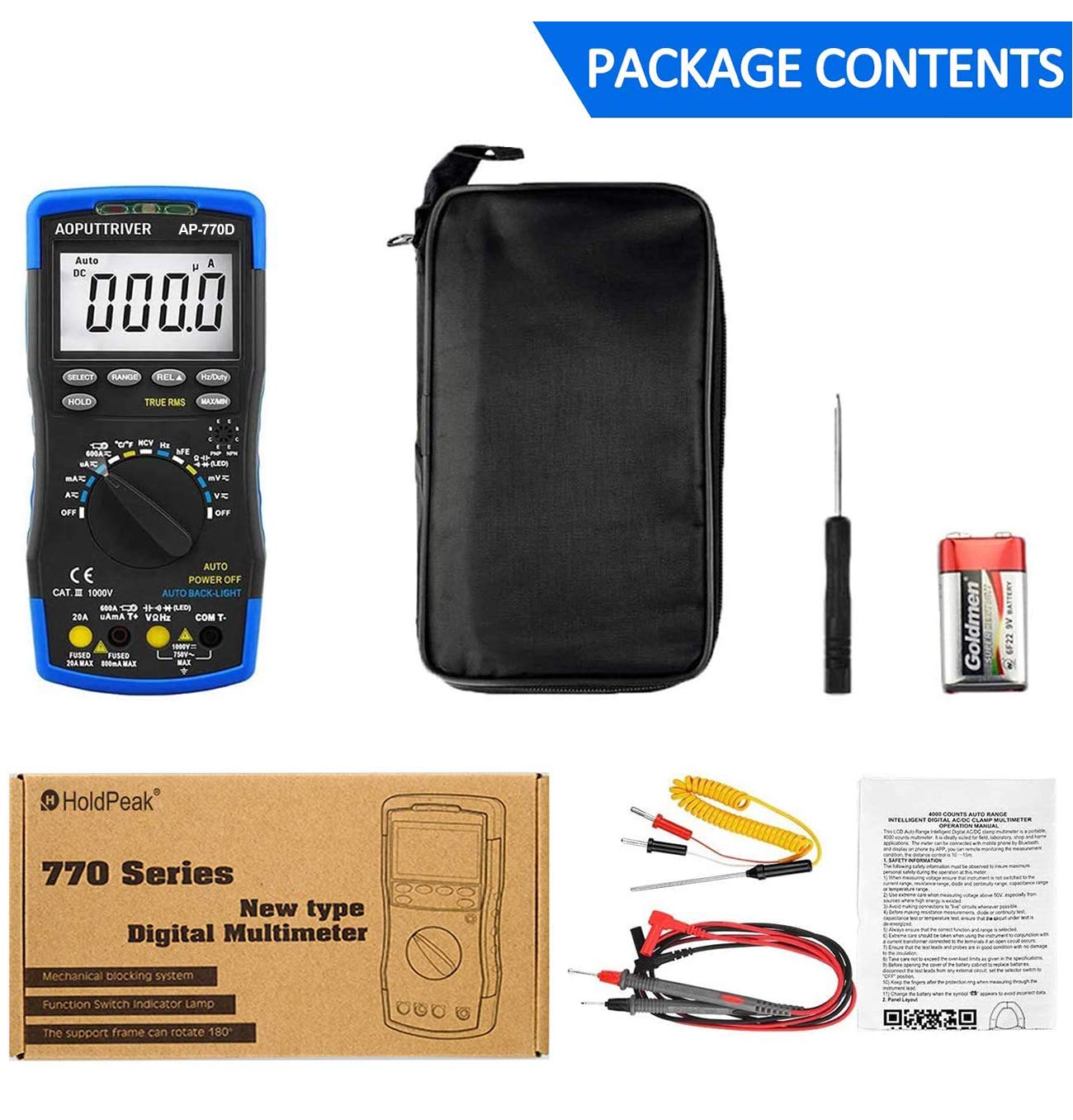
Figure 2.1: Contents of the AP-770D package, including the multimeter, test leads, temperature probe, battery, manual, and carrying pouch.
3. ഉൽപ്പന്നം കഴിഞ്ഞുview
Familiarize yourself with the components of your AP-770D Digital Multimeter:

ചിത്രം 3.1: മുൻഭാഗം view of the AP-770D with key functions labeled.
- NCV Red Light: Indicates non-contact voltagഇ കണ്ടെത്തൽ.
- CDS Sensor: Light sensor for auto backlight.
- NCV Green Light: Indicates non-contact voltagഇ കണ്ടെത്തൽ.
- NCV Detection Area: Point for non-contact voltagഇ സെൻസിംഗ്.
- ഡിസ്പ്ലേ: Large LCD for reading measurements.
- കീ തിരഞ്ഞെടുക്കുക: Toggles between functions within a rotary switch position.
- താക്കോൽ പിടിക്കുക: നിലവിലെ ഡിസ്പ്ലേ റീഡിംഗ് മരവിപ്പിക്കുന്നു.
- RANGE Key: Switches between auto-ranging and manual ranging.
- REL ▲ Key: Activates relative measurement mode.
- Hz/Duty Key: Selects frequency or duty cycle measurement.
- MAX/MIN Key: Records maximum and minimum readings.
- Transistor hFE Test Input Jack: For testing transistor gain.
- റോട്ടറി സ്വിച്ച്: Selects the desired measurement function.
- VΩHz Input: വോളിയത്തിനായുള്ള ഇൻപുട്ട് ടെർമിനൽtage, പ്രതിരോധം, ആവൃത്തി, കപ്പാസിറ്റൻസ്, ഡയോഡ്, തുടർച്ച അളവുകൾ.
- COM Input: Common (negative) terminal for all measurements.
- 20A ഇൻപുട്ട് ജാക്ക്: Input terminal for high AC/DC current measurements (up to 20A).
- µA mA T+ Input: Input terminal for microampere/milliampere current and temperature measurements.

Figure 3.2: Dimensions of the AP-770D and its 180° swivel stand.
4. സജ്ജീകരണം
4.1 ബാറ്ററി ഇൻസ്റ്റാളേഷൻ
The AP-770D requires one 9V battery for operation. To install or replace the battery:
- മൾട്ടിമീറ്റർ ഓഫ് ചെയ്തിട്ടുണ്ടെന്നും ടെസ്റ്റ് ലീഡുകൾ വിച്ഛേദിക്കപ്പെട്ടിട്ടുണ്ടെന്നും ഉറപ്പാക്കുക.
- യൂണിറ്റിന്റെ പിൻഭാഗത്ത് ബാറ്ററി കമ്പാർട്ട്മെന്റ് കവർ കണ്ടെത്തുക.
- ബാറ്ററി കവർ ഉറപ്പിക്കുന്ന സ്ക്രൂ അഴിക്കാൻ ഒരു സ്ക്രൂഡ്രൈവർ ഉപയോഗിക്കുക.
- Remove the cover and insert the 9V battery, observing correct polarity.
- ബാറ്ററി കവർ മാറ്റി സ്ക്രീൻ ശക്തമാക്കുക.
4.2 പ്രാരംഭ പവർ-ഓൺ
Turn the rotary switch from the 'OFF' position to any desired measurement function. The display will illuminate. The meter features an auto backlight that activates in low-light conditions.
5 ഓപ്പറേറ്റിംഗ് മോഡുകൾ
The AP-770D offers a variety of measurement functions. Always ensure the correct function is selected and test leads are connected to the appropriate input jacks.
5.1 വോളിയംtagഇ മെഷർമെന്റ് (എസി/ഡിസി)
വോളിയം അളക്കാൻtage:
- Set the rotary switch to the 'V~' (AC Voltage) or 'V∓' (DC Voltagഇ) സ്ഥാനം.
- Connect the red test lead to the 'VΩHz' input jack and the black test lead to the 'COM' input jack.
- അളക്കേണ്ട സർക്യൂട്ടിലോ ഘടകത്തിലോ ഉടനീളം ടെസ്റ്റ് പ്രോബുകൾ ബന്ധിപ്പിക്കുക.
- വാല്യം വായിക്കുകtagഡിസ്പ്ലേയിലെ ഇ മൂല്യം.
5.2 കറന്റ് മെഷർമെന്റ് (എസി/ഡിസി)
കറൻ്റ് അളക്കാൻ:
- Set the rotary switch to the appropriate current range (µA, mA, or A). Use the 'SELECT' button to toggle between AC and DC current if applicable.
- Connect the red test lead to the 'µA mA T+' or '20A' input jack (depending on expected current) and the black test lead to the 'COM' input jack.
- Connect the test probes in series with the circuit to be measured.
- ഡിസ്പ്ലേയിലെ നിലവിലെ മൂല്യം വായിക്കുക.
5.3 പ്രതിരോധം അളക്കൽ
പ്രതിരോധം അളക്കാൻ:
- Set the rotary switch to the 'Ω' (Resistance) position.
- Connect the red test lead to the 'VΩHz' input jack and the black test lead to the 'COM' input jack.
- Connect the test probes across the component to be measured. Ensure the circuit is de-energized.
- ഡിസ്പ്ലേയിലെ പ്രതിരോധ മൂല്യം വായിക്കുക.
5.4 ശേഷി അളക്കൽ
കപ്പാസിറ്റൻസ് അളക്കാൻ:
- Set the rotary switch to the '––||––' (Capacitance) position.
- Connect the red test lead to the 'VΩHz' input jack and the black test lead to the 'COM' input jack.
- Connect the test probes across the capacitor. Ensure the capacitor is discharged before testing.
- ഡിസ്പ്ലേയിലെ കപ്പാസിറ്റൻസ് മൂല്യം വായിക്കുക.
5.5 Frequency and Duty Cycle Measurement
To measure frequency or duty cycle:
- Set the rotary switch to the 'Hz' position.
- Connect the red test lead to the 'VΩHz' input jack and the black test lead to the 'COM' input jack.
- Connect the test probes across the signal source.
- Press the 'Hz/Duty' button to toggle between frequency and duty cycle readings.
5.6 ഡയോഡ് ടെസ്റ്റ്
To perform a diode test:
- Set the rotary switch to the '→|–' (Diode) position.
- Connect the red test lead to the 'VΩHz' input jack and the black test lead to the 'COM' input jack.
- ചുവന്ന പ്രോബ് ഡയോഡിന്റെ ആനോഡിലേക്കും കറുത്ത പ്രോബ് കാഥോഡിലേക്കും ബന്ധിപ്പിക്കുക.
- A forward voltage drop will be displayed for a good diode. Reverse the probes; the display should show 'OL' (Open Loop).
5.7 തുടർച്ച പരിശോധന
ഒരു തുടർച്ച പരിശോധന നടത്താൻ:
- Set the rotary switch to the '▪))' (Continuity) position.
- Connect the red test lead to the 'VΩHz' input jack and the black test lead to the 'COM' input jack.
- Connect the test probes across the circuit or component.
- If continuity exists (resistance below a certain threshold), the buzzer will sound.
5.8 താപനില അളക്കൽ
താപനില അളക്കാൻ:
- Set the rotary switch to the '°C/°F' (Temperature) position.
- Connect the K-type thermocouple to the 'µA mA T+' and 'COM' input jacks, observing polarity.
- താപനില അളക്കേണ്ട വസ്തുവിൽ അല്ലെങ്കിൽ അതിൽ തെർമോകപ്പിൾ അഗ്രം വയ്ക്കുക.
- Read the temperature value on the display. Use the 'SELECT' button to switch between Celsius and Fahrenheit.

Figure 5.1: Measuring temperature of a liquid using the AP-770D's temperature probe.
5.9 നോൺ-കോൺടാക്റ്റ് വോളിയംtagഇ (NCV) കണ്ടെത്തൽ
To detect AC voltage without contact:
- Set the rotary switch to the 'NCV' position.
- Move the NCV detection area (top of the meter) close to the conductor being tested.
- The NCV red and green lights will flash, and the buzzer will sound, indicating the presence of AC voltage. The intensity of the indication increases with stronger voltage.

Figure 5.2: Using the NCV function to detect live wires without direct contact.
5.10 hFE Test (Transistor Gain)
To test transistor hFE:
- Set the rotary switch to the 'hFE' position.
- Insert the transistor leads (Emitter, Base, Collector) into the corresponding holes in the 'Transistor hFE Test Input Jack'.
- Read the hFE value on the display.
6 സ്പെസിഫിക്കേഷനുകൾ
| ഫീച്ചർ | മൂല്യം |
|---|---|
| പ്രദർശന എണ്ണം | 40,000 എണ്ണം |
| യഥാർത്ഥ RMS | അതെ |
| ഓട്ടോ റേഞ്ച് | അതെ |
| എൻ.സി.വി | അതെ |
| എസി/ഡിസി വോളിയംtage | 1000V വരെ |
| എസി / ഡിസി കറന്റ് | 20A വരെ |
| പ്രതിരോധം | 60MΩ വരെ |
| കപ്പാസിറ്റൻസ് | Up to 60mF |
| ആവൃത്തി | 10MHz വരെ |
| താപനില | Yes (with K-type thermocouple) |
| ഡയോഡ് ടെസ്റ്റ് | അതെ |
| തുടർച്ചയായ പരിശോധന | Yes (with buzzer) |
| hFE ടെസ്റ്റ് | അതെ |
| യാന്ത്രിക ബാക്ക്ലൈറ്റ് | അതെ |
| ഓട്ടോ പവർ ഓഫ് | അതെ |
| സുരക്ഷാ മാനദണ്ഡം | IEC-1010, CAT III 1000V |
| പവർ ഉറവിടം | 9V ബാറ്ററി |
| അളവുകൾ | 20cm x 9cm x 4cm (ഏകദേശം) |
| ഭാരം | 350 ഗ്രാം |
7. പരിപാലനം
7.1 വൃത്തിയാക്കൽ
Wipe the meter's casinപരസ്യത്തോടുകൂടിയ ജിamp തുണിയും നേരിയ ഡിറ്റർജന്റും ഉപയോഗിക്കുക. അബ്രാസീവ് വസ്തുക്കളോ ലായകങ്ങളോ ഉപയോഗിക്കരുത്. ഉപയോഗിക്കുന്നതിന് മുമ്പ് മീറ്റർ പൂർണ്ണമായും ഉണങ്ങിയെന്ന് ഉറപ്പാക്കുക.
7.2 ബാറ്ററി മാറ്റിസ്ഥാപിക്കൽ
When the battery symbol appears on the display, replace the 9V battery as described in Section 4.1.
7.3 ഫ്യൂസ് മാറ്റിസ്ഥാപിക്കൽ
If the current measurement function fails, the fuse may need replacement. Refer to the full user manual for detailed instructions on fuse replacement. Always use fuses with the specified ratings (e.g., Fused 20A MAX, Fused 500mA MAX).

Figure 7.1: The mechanical blocking system helps prevent incorrect lead insertion, enhancing safety during use.
8. പ്രശ്നപരിഹാരം
- ഡിസ്പ്ലേ ഇല്ല: Check battery installation and charge level. Replace battery if necessary.
- 'OL' on Display: Indicates an over-range condition or open circuit. Select a higher range or check connections.
- തെറ്റായ വായനകൾ: Ensure correct function and range are selected. Verify test lead connections and integrity.
- Current Measurement Failure: Check the fuse. Replace if blown (refer to Section 7.3).
9. വാറൻ്റിയും പിന്തുണയും
For warranty information or technical support, please refer to the contact details provided in your product packaging or visit the AOPUTTRIVER official website. Do not attempt to repair the device yourself, as this may void the warranty and pose a safety risk.


