1. ആമുഖം
This manual provides comprehensive instructions for the Bkiyougo 433MHz Wireless RF Remote Control Switch Kit. This kit includes a compact receiver module and a remote control transmitter, designed for various applications requiring wireless control of electrical devices.
പ്രധാന സവിശേഷതകളിൽ ഇവ ഉൾപ്പെടുന്നു:
- എളുപ്പമുള്ള പ്രവർത്തനം: Simple setup and programming with four distinct operating modes: Momentary, Toggle, Latched, and Delay.
- ഫ്ലെക്സിബിൾ ഡിസൈൻ: Mini-sized receiver module (25mm x 15mm x 3mm) for easy integration into DIY projects. Supports a wide DC voltag3.6V മുതൽ 24V വരെയുള്ള ഇ ശ്രേണി.
- ഒന്നിലധികം ഉപയോക്തൃ നിയന്ത്രണം: One receiver can store up to 10 transmitters, allowing multiple users to control a single device. Conversely, one transmitter can control multiple receivers simultaneously.
- വിപുലീകരിച്ച ശ്രേണി: Offers a control range of up to 50 meters in open areas, with strong signal penetration through walls, floors, and doors.
- Secure Technology: Utilizes EV1527 learning code for enhanced security.

Image 1.1: Bkiyougo 433MHz Wireless RF Remote Control Switch Kit components.
2. ഉൽപ്പന്ന സവിശേഷതകൾ
The following table details the technical specifications of the Bkiyougo 433MHz Wireless RF Remote Control Switch Kit.

Image 2.1: Detailed product parameters.
| പരാമീറ്റർ | മൂല്യം |
|---|---|
| ഓപ്പറേറ്റിംഗ് വോളിയംtage | ഡിസി 3.6V - 24V |
| പരമാവധി ലോഡ് കറന്റ് | 2A |
| ക്വിസെൻ്റ് കറൻ്റ് | < 5mA |
| പ്രവർത്തന ആവൃത്തി | 433MHz |
| റിസീവർ സെൻസിറ്റിവിറ്റി | -108dBm |
| ഇൻപുട്ട് വോളിയംtage | ഡിസി 3.6V - 24V |
| Putട്ട്പുട്ട് വോളിയംtage | DC 3.6V - 24V (Matches Input Voltage) |
| മോഡുലേഷൻ മോഡ് | ചോദിക്കുക (Ampലിറ്റ്യൂഡ് ഷിഫ്റ്റ് കീയിംഗ്) |
| Supported Encoding | 1527 Learning Code |
| Max Stored Remotes | 10 ട്രാൻസ്മിറ്ററുകൾ |
| ഓപ്പറേറ്റിംഗ് മോഡുകൾ | Momentary, Toggle, Latched, Delay (5/10/15/20s) |
| പഠന ശൈലി | Keystroke Learning |
| പ്രവർത്തന താപനില | -20°C മുതൽ 80°C വരെ |
| റിസീവർ അളവുകൾ | 25mm (L) x 15mm (W) x 3mm (H) |
| ആൻ്റിന നീളം | 175 മി.മീ |
| വയർ നീളം | 75 മി.മീ |
| ട്രാൻസ്മിറ്റർ ബാറ്ററി | 2 x CR2032 (ഉൾപ്പെടുത്തിയിരിക്കുന്നു) |
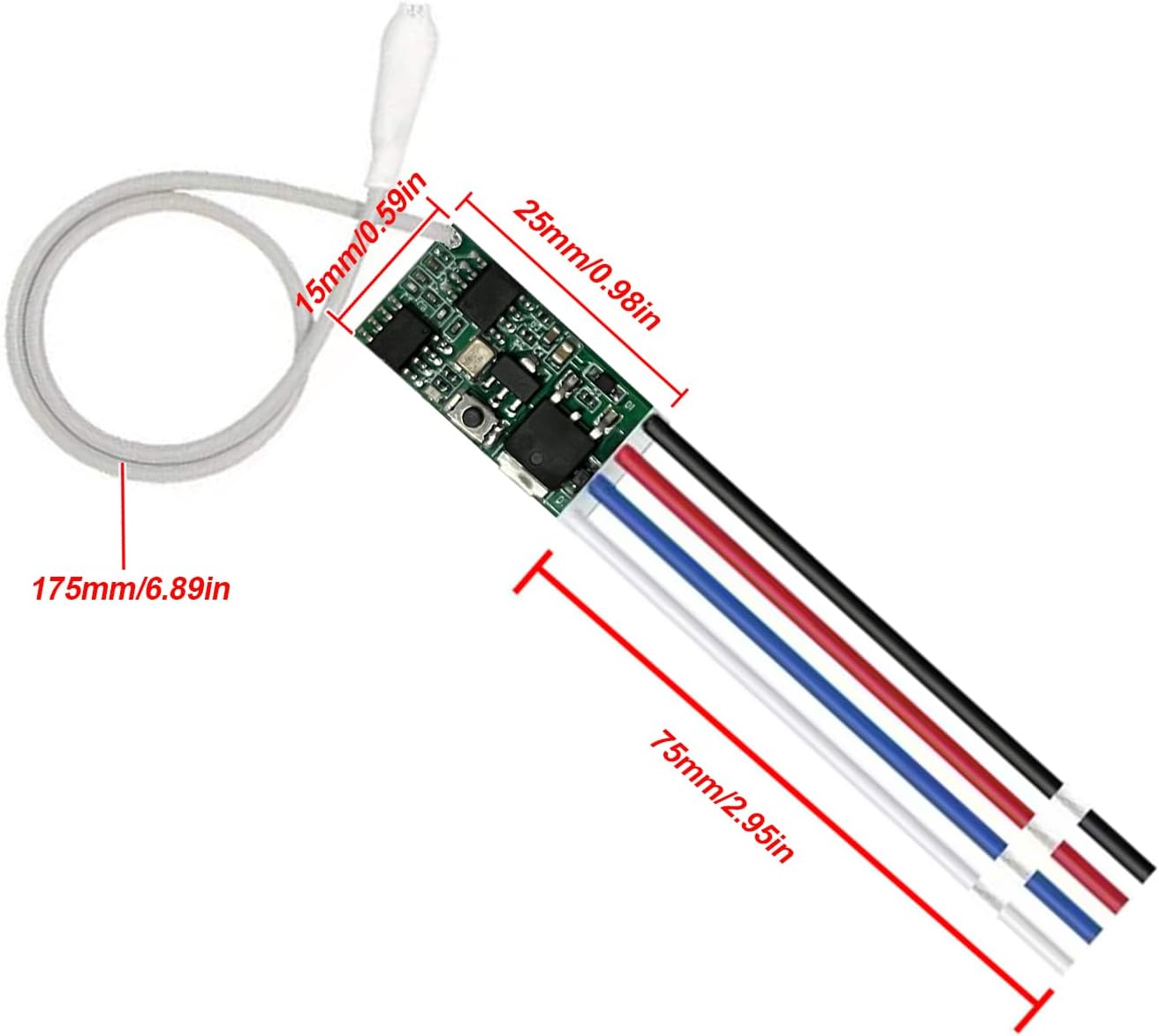
Image 2.2: Receiver module dimensions.
3. സജ്ജീകരണവും വയറിംഗും
3.1 ട്രാൻസ്മിറ്റർ ബാറ്ററി ഇൻസ്റ്റാളേഷൻ
The remote control transmitter requires two CR2032 batteries. To install or replace them, locate the screw port on the back of the transmitter, disassemble the casing, and insert the batteries according to the polarity markings.
3.2 റിസീവർ വയറിംഗ്
The receiver module features two wiring terminals for easy connection. It operates within a DC 3.6V to 24V range. Ensure correct polarity when connecting power and load.

Image 3.1: Receiver module wiring labels.
3.2.1 Wiring for Electromagnets
When connecting to an electromagnet, ensure a diode (e.g., IN4007) is used in parallel with the electromagnet coil to protect the receiver from back-EMF. Connect the input power to IN+ and IN-, and the electromagnet to OUT+ and OUT- as shown in the diagram.
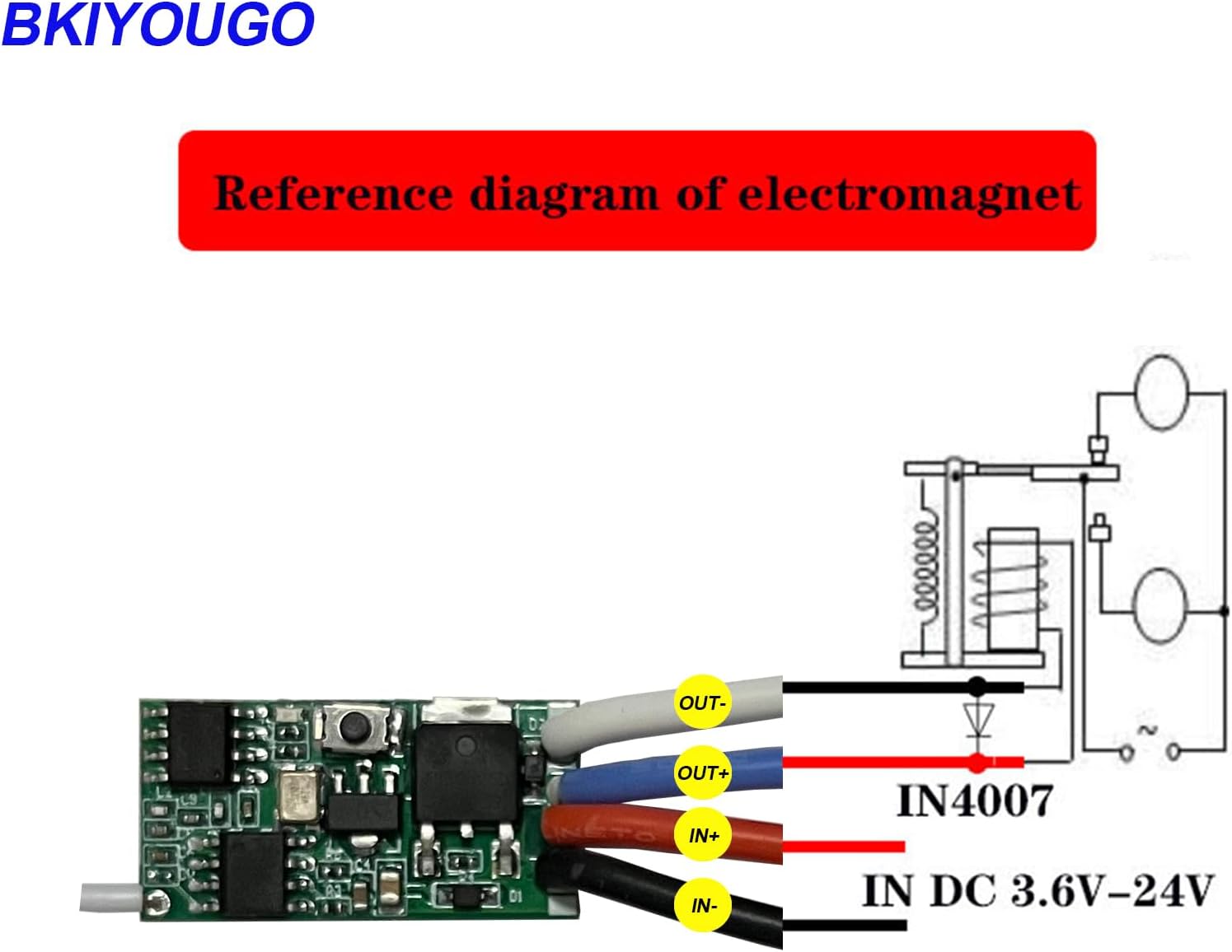
Image 3.2: Electromagnet wiring diagram.
3.2.2 Wiring for LED Lights
For controlling LED lights, connect the DC power source to IN+ and IN-, and the LED light to OUT+ and OUT-. The output voltage will match the input voltage. The maximum load for LED lights is 3A.

Image 3.3: LED light control wiring diagram.
4. Operating Modes and Programming
The receiver supports four operating modes, each programmed by pressing the learning button a specific number of times. The learning button is a small black button located on the receiver module (refer to Image 3.1).
4.1 Momentary Mode
In Momentary Mode, the output is active only while the remote button is pressed and held. Releasing the button deactivates the output.
- പ്രോഗ്രാമിംഗ്: Press the learning button on the receiver 1 തവണ. Wait approximately 3 seconds. Then, press any button on the remote control. The indicator light on the receiver will flash to confirm successful programming.

Image 4.1: Momentary Mode operation and programming.
4.2 ടോഗിൾ മോഡ്
In Toggle Mode, pressing the remote button once turns the output ON. Pressing the same button again turns the output OFF.
- പ്രോഗ്രാമിംഗ്: Press the learning button on the receiver 2 തവണ. Wait approximately 3 seconds. Then, press any button on the remote control. The indicator light on the receiver will flash to confirm successful programming.

Image 4.2: Toggle Mode operation and programming.
4.3 Latched Mode
Latched Mode uses two separate buttons on the remote: one to turn the output ON and another to turn it OFF. For the provided remote, this typically means the 'ON' button activates and the 'OFF' button deactivates.
- പ്രോഗ്രാമിംഗ്: Press the learning button on the receiver 3 തവണ. Wait approximately 3 seconds. First, press the 'ON' button on the remote control. Then, press the 'OFF' button on the remote control. The indicator light on the receiver will flash to confirm successful programming.

Image 4.3: Latched Mode operation and programming.
4.4 കാലതാമസ മോഡ്
In Delay Mode, pressing the remote button once turns the output ON, and it automatically turns OFF after a preset delay (5, 10, 15, or 20 seconds).
- പ്രോഗ്രാമിംഗ്:
- For 5-second delay: Press the learning button 4 തവണ.
- For 10-second delay: Press the learning button 5 തവണ.
- For 15-second delay: Press the learning button 6 തവണ.
- For 20-second delay: Press the learning button 7 തവണ.
- After selecting the desired delay by pressing the learning button, wait approximately 3 seconds. Then, press any button on the remote control. The indicator light on the receiver will flash to confirm successful programming.

Image 4.4: Delay Mode operation and programming.
4.5 Clearing Stored Transmitters
To clear all stored transmitters from the receiver's memory, press the learning button on the receiver 8 തവണ. The indicator light will flash to confirm that all previously programmed remotes have been cleared.
5. അപേക്ഷകൾ
This wireless RF remote control switch is suitable for a wide range of applications, including:
- Controlling LED lights, lamp beads, and Christmas tree light strings.
- Lighting control switches for various environments.
- Home, office, and hotel lighting remodeling projects.
- Automotive applications such as controlling doors, tailgates, sunroofs, and interior lighting.
- DIY projects requiring remote power switching.
- ഗാരേജ് വാതിൽ തുറക്കുന്നവർ.

Image 5.1: Various application scenarios.

Image 5.2: Application for garage door control.

Image 5.3: Application for ceiling fan control.
6. പരിപാലനം
To ensure optimal performance and longevity of your Bkiyougo Remote Control Switch Kit, consider the following maintenance guidelines:
- ബാറ്ററി മാറ്റിസ്ഥാപിക്കൽ: Replace the CR2032 batteries in the remote control transmitter when its range decreases or it becomes unresponsive. Refer to Section 3.1 for instructions.
- ആന്റിന കെയർ: The receiver's antenna wire is delicate. Handle it with care to prevent breakage, which can significantly reduce the operating range. Avoid bending or pulling the antenna excessively.
- വൃത്തിയാക്കൽ: Keep the receiver module and remote control clean and free from dust and debris. Use a soft, dry cloth for cleaning. Avoid using liquids or abrasive cleaners.
- പരിസ്ഥിതി വ്യവസ്ഥകൾ: Operate the device within the specified temperature range (-20°C to 80°C) and avoid exposure to excessive moisture or direct sunlight.
7. പ്രശ്നപരിഹാരം
If you encounter issues with your Bkiyougo Remote Control Switch Kit, refer to the following common problems and solutions:
- Issue: Remote control not responding or short range.
പരിഹാരം: Check the batteries in the remote control and replace them if necessary. Ensure the receiver's antenna is intact and not damaged. Obstructions like thick walls or metal structures can reduce range; try repositioning the receiver or reducing the distance. - Issue: Programming modes not setting correctly.
പരിഹാരം: When pressing the learning button multiple times for different modes, ensure each press is rapid and distinct. Pauses between presses may cause the receiver to interpret it as a single press for Momentary Mode. Refer to Section 4 for precise programming steps. - Issue: Device remains ON or OFF unexpectedly after initial use.
പരിഹാരം: This could indicate a short circuit or incorrect wiring. Double-check all connections according to the wiring diagrams in Section 3. If the issue persists, the receiver module may be damaged. - Issue: Output voltage does not match input voltage, or device does not function as a simple relay.
വ്യക്തത: This device provides power (matching input voltage) to the output when activated, rather than acting as a dry contact relay that simply connects two separate circuits. If your application requires a true relay function (e.g., switching a positive power line independently), you may need to integrate an external relay with this module. The receiver switches the negative side of the output.
8. വാറൻ്റിയും പിന്തുണയും
For warranty information, please refer to the documentation included with your purchase or contact the retailer. For technical support or further assistance, please visit the official Bkiyougo brand store or contact their customer service.
Bkiyougo Brand Store: Visit Bkiyougo Store on Amazon