1. ആമുഖം
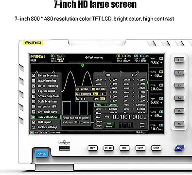
The FNIRSI-1014D is a versatile 2-in-1 device combining a digital oscilloscope and a signal generator. It features a 7-inch 800x480 resolution color TFT LCD, dual channels with 100MHz bandwidth, and a 1GS/s sampling rate. This manual provides essential information for the proper setup, operation, and maintenance of your device.
This device is suitable for various applications including electronic DIY, appliance repair, car repair, equipment debugging, scientific research, and product development.

Figure 1: FNIRSI-1014D demonstrating its applicability in multiple fields such as electronic DIY, appliance repair, and scientific research.
2 സുരക്ഷാ വിവരങ്ങൾ
ഉപകരണം പ്രവർത്തിപ്പിക്കുന്നതിന് മുമ്പ് എല്ലാ സുരക്ഷാ നിർദ്ദേശങ്ങളും വായിച്ച് മനസ്സിലാക്കുക. ഈ നിർദ്ദേശങ്ങൾ പാലിക്കുന്നതിൽ പരാജയപ്പെടുന്നത് വൈദ്യുതാഘാതം, തീപിടുത്തം അല്ലെങ്കിൽ ഉപകരണത്തിന് കേടുപാടുകൾ എന്നിവയ്ക്ക് കാരണമായേക്കാം.
- നൽകിയിരിക്കുന്ന പവർ അഡാപ്റ്ററും കേബിളുകളും മാത്രം ഉപയോഗിക്കുക.
- വെറ്റ് അല്ലെങ്കിൽ ഡിയിൽ ഉപകരണം പ്രവർത്തിപ്പിക്കരുത്amp വ്യവസ്ഥകൾ.
- അമിതമായി ചൂടാക്കുന്നത് തടയാൻ ശരിയായ വായുസഞ്ചാരം ഉറപ്പാക്കുക.
- നേരിട്ടുള്ള സൂര്യപ്രകാശത്തിലോ ഉയർന്ന താപനിലയിലോ ഉപകരണം തുറന്നുകാട്ടുന്നത് ഒഴിവാക്കുക.
- ഉപകരണം തുറക്കാനോ പരിഷ്ക്കരിക്കാനോ ശ്രമിക്കരുത്. എല്ലാ സേവനങ്ങളും യോഗ്യതയുള്ള ഉദ്യോഗസ്ഥർക്ക് റഫർ ചെയ്യുക.
- Always connect the ground lead of the probe before connecting the signal lead.
3. പാക്കേജ് ഉള്ളടക്കം
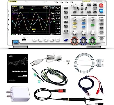
Carefully unpack the device and check for the following items. If any item is missing or damaged, contact your supplier immediately.
- FNIRSI-1014D Digital Oscilloscope
- 100MHz Oscilloscope Probes (x2)
- യുഎസ്ബി ചാർജർ
- USB കേബിൾ
- അലിഗേറ്റർ ക്ലിപ്പ് കേബിൾ
- ഉപയോക്തൃ മാനുവൽ (ഈ പ്രമാണം)

Figure 2: The FNIRSI-1014D oscilloscope shown with its complete set of accessories, including probes, cables, and power adapter.
4. ഡിവൈസ് ഓവർview
4.1 ഫ്രണ്ട് പാനൽ
The front panel features the 7-inch LCD display, control buttons, rotary encoders, and input connectors for the oscilloscope channels and signal generator output.
ചിത്രം 3: മുൻഭാഗം view of the FNIRSI-1014D, highlighting the display, control panel, and input/output ports.
4.2 പിൻ പാനൽ
The rear panel typically includes the power input and possibly a USB port for data transfer or firmware updates.
ചിത്രം 4: പിൻഭാഗം view of the FNIRSI-1014D, showing the power input and identification label.
5. സജ്ജീകരണം
- പവർ കണക്ഷൻ: Connect the provided USB charger and cable to the device's power input port. Plug the charger into a suitable power outlet.
- പവർ ഓൺ: Press the 'POWER' button located on the front panel to turn on the device.
- അന്വേഷണ കണക്ഷൻ: For oscilloscope measurements, connect the 100MHz probes to the CH1 and CH2 BNC input connectors. Ensure the probes are securely twisted into place.
- പ്രോബ് കോമ്പൻസേഷൻ: Before taking measurements, it is recommended to compensate the probes. Connect the probe tip to the probe compensation output (usually a square wave signal on the device) and adjust the probe's compensation trimmer until a flat-top square wave is displayed on the screen.
6. അടിസ്ഥാന പ്രവർത്തനം
6.1 ഓസിലോസ്കോപ്പ് മോഡ്
The FNIRSI-1014D operates primarily as a dual-channel digital oscilloscope. The main display shows the waveforms, measurement parameters, and control settings.
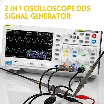
Figure 5: The oscilloscope display showing various menu options for settings like coupling, scale, and trigger.
- ലംബ നിയന്ത്രണങ്ങൾ: Use the CH1/CH2 buttons and associated rotary encoders to adjust vertical position and voltage scale (Volts/Div) for each channel.
- തിരശ്ചീന നിയന്ത്രണങ്ങൾ: Use the TIME/DIV rotary encoder to adjust the horizontal time base.
- ട്രിഗർ ക്രമീകരണങ്ങൾ: The 'EDGE' button allows selection of rising or falling edge trigger. 'MODE' button selects trigger mode (Auto, Normal, Single).
- ഓട്ടോ ബട്ടൺ: Pressing the 'AUTO' button automatically adjusts the vertical and horizontal settings to display a stable waveform.
- അളക്കൽ പ്രവർത്തനങ്ങൾ: The device supports various automatic measurements. Refer to the on-screen menu for available parameters.
6.2 സിഗ്നൽ ജനറേറ്റർ മോഡ്
The FNIRSI-1014D includes a built-in 10MHz DDS signal generator capable of producing 14 types of waveforms.

Figure 6: The FNIRSI-1014D connected with probes, demonstrating its signal generation capabilities.
- Activating Generator: Press the 'GEN' button to access the signal generator functions.
- തരംഗരൂപ തിരഞ്ഞെടുപ്പ്: Use the navigation buttons to select the desired waveform type (e.g., Sine, Square, Triangle).
- ആവൃത്തി/Ampഅക്ഷാംശ ക്രമീകരണം: Use the rotary encoders to set the frequency and amplitude of the generated signal.
- ഔട്ട്പുട്ട് കണക്ഷൻ: Connect the signal generator output (typically a dedicated BNC port or shared with CH2 in generator mode) to the circuit or device under test.
7. പരിപാലനം
- വൃത്തിയാക്കൽ: Use a soft, dry cloth to clean the device's exterior. For stubborn dirt, a slightly damp ഉപകരണത്തിനുള്ളിൽ ദ്രാവകം പ്രവേശിക്കുന്നില്ലെന്ന് ഉറപ്പാക്കാൻ, നേരിയ ഡിറ്റർജന്റ് ഉള്ള തുണി ഉപയോഗിക്കാം.
- സംഭരണം: ഉപയോഗത്തിലില്ലാത്തപ്പോൾ നേരിട്ടുള്ള സൂര്യപ്രകാശത്തിൽ നിന്നും കടുത്ത താപനിലയിൽ നിന്നും മാറി തണുത്തതും വരണ്ടതുമായ സ്ഥലത്ത് ഉപകരണം സൂക്ഷിക്കുക.
- പ്രോബ് കെയർ: Handle probes carefully. Avoid bending or stressing the cables. Keep probe tips clean.
- ബാറ്ററി (ബാധകമെങ്കിൽ): If the device has an internal rechargeable battery, follow manufacturer guidelines for charging and storage to prolong battery life.
8. പ്രശ്നപരിഹാരം
- ശക്തിയില്ല:
- Ensure the power adapter is correctly connected and the power outlet is functional.
- ശരിയായ ഇടപെടലിനായി പവർ ബട്ടൺ പരിശോധിക്കുക.
- വേവ്ഫോം ഡിസ്പ്ലേ ഇല്ല:
- Verify probes are correctly connected to the input channels and the signal source.
- Adjust the vertical (Volts/Div) and horizontal (Time/Div) scales.
- Check trigger settings (Mode, Level, Edge). Try pressing the 'AUTO' button.
- Ensure the input coupling (AC/DC) is appropriate for the signal.
- വികലമായ തരംഗരൂപം:
- Perform probe compensation.
- Check for proper grounding of the device and the circuit under test.
- Ensure the signal amplitude does not exceed the input range of the oscilloscope.
9 സ്പെസിഫിക്കേഷനുകൾ
Figure 7: Detailed specifications of the FNIRSI-1014D, including display, performance, and accessory information.
| ഫീച്ചർ | സ്പെസിഫിക്കേഷൻ |
|---|---|
| മോഡൽ | FNIRSI-1014D |
| ചാനലുകൾ | 2 |
| LCD വലിപ്പം | 7 ഇഞ്ച് |
| LCD റെസല്യൂഷൻ | 800 * 480 |
| ഡിസ്പ്ലേ ടെക്നോളജി | ടിഎഫ്ടി എൽസിഡി |
| ബാൻഡ്വിഡ്ത്ത് | 100MHz |
| Sampലിംഗ് നിരക്ക് | 1GS/s |
| ഉദയ സമയം | <3.5s |
| സംഭരണത്തിൻ്റെ ആഴം | 240kbit |
| ഇൻപുട്ട് പ്രതിരോധം | 1MΩ |
| സംവേദനക്ഷമത | 50 എംവി - 500വി |
| സമയ അടിസ്ഥാനം | 50S - 10nS |
| ട്രിഗർ മോഡ് | Single/Normal/Auto |
| ട്രിഗർ എഡ്ജ് | ഉയരുന്നു/വീഴുന്നു |
| ഇണചേരൽ | എസി/ഡിസി |
| Highest Test Voltage | 1X: 40V, 10X: 400V |
| കഴ്സർ | Position XY Trigger Y |
| റോൾ മോഡ് | പിന്തുണച്ചു |
| One-button AUTO | പിന്തുണച്ചു |
| വേവ്ഫോം സംഭരണം | 1000 pictures + 1000 waveforms |
| വേവ്ഫോം മാനേജർ | പിന്തുണച്ചു |
| വാല്യംtagഇ കൃത്യത | ±5% |
| ഫ്രീക്വൻസി പ്രിസിഷൻ | ±0.01% High precision |
| പാരാമീറ്റർ അളവുകൾ | 12 kinds in total |
| സിഗ്നൽ ജനറേറ്റർ | 14 kinds of waveforms |
| ഔട്ട്പുട്ട് ക്യാപ്ചർ ചെയ്യുക | പിന്തുണച്ചു |
| വിപുലീകരണം | യുഎസ്ബി എക്സ്പോർട്ട് |
| വൈദ്യുതി വിതരണം | 5V 2A/3A/4A |
| അളവുകൾ | 310 മിമി * 145 മിമി * 70 മിമി |
| ആക്സസറികൾ | 2x 100M Probes, USB Charger, User Manual |
10. വാറൻ്റിയും പിന്തുണയും
FNIRSI products are designed for reliability and performance. For warranty information, technical support, or service inquiries, please refer to the contact information provided with your purchase or visit the official FNIRSI webസൈറ്റ്. വാറന്റി ക്ലെയിമുകൾക്കായി നിങ്ങളുടെ വാങ്ങലിന്റെ തെളിവ് സൂക്ഷിക്കുക.


