![]() HT64
HT64
ഉപയോക്തൃ മാനുവൽ![]()
![]()

മുൻകരുതലുകളും സുരക്ഷാ നടപടികളും
ഇലക്ട്രോണിക് അളക്കുന്ന ഉപകരണങ്ങൾക്ക് പ്രസക്തമായ IEC/EN61010-1 നിർദ്ദേശങ്ങൾ പാലിച്ചാണ് ഉപകരണം രൂപകൽപ്പന ചെയ്തിരിക്കുന്നത്. നിങ്ങളുടെ സുരക്ഷയ്ക്കും ഉപകരണത്തിന് കേടുപാടുകൾ സംഭവിക്കുന്നത് തടയാനും, ഈ മാനുവലിൽ വിവരിച്ചിരിക്കുന്ന നടപടിക്രമങ്ങൾ ശ്രദ്ധാപൂർവ്വം പിന്തുടരുക, ചിഹ്നത്തിന് മുമ്പുള്ള എല്ലാ കുറിപ്പുകളും വായിക്കുക ![]() അതീവ ശ്രദ്ധയോടെ.
അതീവ ശ്രദ്ധയോടെ.
അളവുകൾ നടത്തുന്നതിന് മുമ്പും ശേഷവും, ഇനിപ്പറയുന്ന നിർദ്ദേശങ്ങൾ ശ്രദ്ധാപൂർവ്വം നിരീക്ഷിക്കുക:
- ഈർപ്പമുള്ള അന്തരീക്ഷത്തിൽ ഒരു അളവും നടത്തരുത്.
- വാതകമോ സ്ഫോടനാത്മക വസ്തുക്കളോ കത്തുന്ന വസ്തുക്കളോ പൊടി നിറഞ്ഞ ചുറ്റുപാടുകളോ ഉണ്ടെങ്കിൽ അളവുകളൊന്നും നടത്തരുത്.
- അളവുകളൊന്നും നടക്കുന്നില്ലെങ്കിൽ, അളക്കുന്ന സർക്യൂട്ടുമായുള്ള സമ്പർക്കം ഒഴിവാക്കുക.
- ഉപയോഗിക്കാത്ത അളക്കുന്ന പേടകങ്ങൾ, സർക്യൂട്ടുകൾ മുതലായവ ഉപയോഗിച്ച് തുറന്ന ലോഹ ഭാഗങ്ങളുമായുള്ള സമ്പർക്കം ഒഴിവാക്കുക.
- ഉപകരണത്തിൽ രൂപഭേദം, ബ്രേക്കുകൾ, പദാർത്ഥങ്ങളുടെ ചോർച്ച, സ്ക്രീനിൽ ഡിസ്പ്ലേ ഇല്ലാത്തത് മുതലായ അപാകതകൾ കണ്ടെത്തിയാൽ ഒരു അളവെടുപ്പും നടത്തരുത്.
- വോള്യം അളക്കുമ്പോൾ പ്രത്യേകം ശ്രദ്ധിക്കുകtagവൈദ്യുത ആഘാതത്തിന് സാധ്യതയുള്ളതിനാൽ 20V യേക്കാൾ കൂടുതലാണ്.
ഈ മാനുവലിലും ഉപകരണത്തിലും ഇനിപ്പറയുന്ന ചിഹ്നങ്ങൾ ഉപയോഗിക്കുന്നു:
![]() മുന്നറിയിപ്പ്: ഈ മാനുവലിൽ നൽകിയിരിക്കുന്ന നിർദ്ദേശങ്ങൾ നിരീക്ഷിക്കുക; അനുചിതമായ ഉപയോഗം ഉപകരണത്തിനോ അതിന്റെ ഘടകങ്ങൾക്കോ കേടുവരുത്തും.
മുന്നറിയിപ്പ്: ഈ മാനുവലിൽ നൽകിയിരിക്കുന്ന നിർദ്ദേശങ്ങൾ നിരീക്ഷിക്കുക; അനുചിതമായ ഉപയോഗം ഉപകരണത്തിനോ അതിന്റെ ഘടകങ്ങൾക്കോ കേടുവരുത്തും.
![]() ഇരട്ട-ഇൻസുലേറ്റഡ് മീറ്റർ
ഇരട്ട-ഇൻസുലേറ്റഡ് മീറ്റർ
![]() എസി വോളിയംtagഇ അല്ലെങ്കിൽ നിലവിലെ
എസി വോളിയംtagഇ അല്ലെങ്കിൽ നിലവിലെ
![]() ഡിസി വോളിയംtagഇ അല്ലെങ്കിൽ നിലവിലെ
ഡിസി വോളിയംtagഇ അല്ലെങ്കിൽ നിലവിലെ
![]() ഭൂമിയുമായുള്ള ബന്ധം
ഭൂമിയുമായുള്ള ബന്ധം
1.1 പ്രാഥമിക നിർദ്ദേശങ്ങൾ
- ഈ ഉപകരണം മലിനീകരണം ഡിഗ്രി 2-ന്റെ പരിതസ്ഥിതിയിൽ ഉപയോഗിക്കുന്നതിന് രൂപകൽപ്പന ചെയ്തിരിക്കുന്നു.
- ഇത് VOL-ന് ഉപയോഗിക്കാംTAGCAT IV 600V, CAT III 1000V എന്നിവയുള്ള ഇൻസ്റ്റാളേഷനുകളിലെ E, CURRENT അളവുകൾ.
- തത്സമയ സിസ്റ്റങ്ങളിൽ പ്രവർത്തനങ്ങൾ നടത്തുന്നതിനും അപകടകരമായ പ്രവാഹങ്ങളിൽ നിന്നും ഉപകരണത്തിന്റെ തെറ്റായ ഉപയോഗത്തിൽ നിന്നും ഉപയോക്താവിനെ പരിരക്ഷിക്കുന്നതിന് നിർദ്ദിഷ്ട പിപിഇ ഉപയോഗിക്കുന്നതിനുമുള്ള നടപടിക്രമങ്ങൾ വിഭാവനം ചെയ്ത സാധാരണ സുരക്ഷാ നിയമങ്ങൾ പാലിക്കാൻ ഞങ്ങൾ ശുപാർശ ചെയ്യുന്നു.
- വോളിയത്തിന്റെ സാന്നിധ്യം സൂചിപ്പിക്കുന്ന അഭാവത്തിൽtagഇ ഓപ്പറേറ്റർക്ക് ഒരു അപകടത്തെ പ്രതിനിധീകരിക്കാം, ലീഡുകളുടെ ശരിയായ കണക്ഷനും അവസ്ഥയും സ്ഥിരീകരിക്കുന്നതിന്, ലൈവ് സിസ്റ്റത്തിൽ അളക്കുന്നതിന് മുമ്പ് എല്ലായ്പ്പോഴും ഒരു തുടർച്ച അളക്കൽ നടത്തുക.
- ഉപകരണത്തിനൊപ്പം നൽകിയിട്ടുള്ള ലീഡുകൾ മാത്രമേ സുരക്ഷാ മാനദണ്ഡങ്ങൾ പാലിക്കുന്നുണ്ടെന്ന് ഉറപ്പുനൽകൂ. അവ നല്ല അവസ്ഥയിലായിരിക്കണം, ആവശ്യമുള്ളപ്പോൾ സമാനമായ മോഡലുകൾ ഉപയോഗിച്ച് മാറ്റിസ്ഥാപിക്കുക.
- നിർദ്ദിഷ്ട വോള്യത്തിൽ കൂടുതലുള്ള സർക്യൂട്ടുകൾ പരീക്ഷിക്കരുത്tagഇ പരിധികൾ.
- § 6.2.1 ൽ സൂചിപ്പിച്ചിരിക്കുന്ന പരിധികൾ കവിയുന്ന പാരിസ്ഥിതിക സാഹചര്യങ്ങളിൽ ഒരു പരിശോധനയും നടത്തരുത്.
- ബാറ്ററി ശരിയായി ചേർത്തിട്ടുണ്ടോയെന്ന് പരിശോധിക്കുക.
- എൽസിഡി ഡിസ്പ്ലേയും റോട്ടറി സ്വിച്ചും ഒരേ ഫംഗ്ഷനാണെന്ന് ഉറപ്പാക്കുക.
1.2 ഉപയോഗ സമയത്ത്
ഇനിപ്പറയുന്ന ശുപാർശകളും നിർദ്ദേശങ്ങളും ശ്രദ്ധാപൂർവ്വം വായിക്കുക:
![]() ജാഗ്രത
ജാഗ്രത
മുൻകരുതൽ കുറിപ്പുകൾ കൂടാതെ/അല്ലെങ്കിൽ നിർദ്ദേശങ്ങൾ പാലിക്കുന്നതിൽ പരാജയപ്പെടുന്നത് ഉപകരണത്തിനും കൂടാതെ/അല്ലെങ്കിൽ അതിന്റെ ഘടകങ്ങൾക്കും കേടുപാടുകൾ വരുത്താം അല്ലെങ്കിൽ ഓപ്പറേറ്റർക്ക് അപകടത്തിന്റെ ഉറവിടമാകാം.
- റോട്ടറി സ്വിച്ച് സജീവമാക്കുന്നതിന് മുമ്പ്, അളക്കുന്ന സർക്യൂട്ടിൽ നിന്ന് ടെസ്റ്റ് ലീഡുകൾ വിച്ഛേദിക്കുക.
- ഉപകരണം അളക്കുന്ന സർക്യൂട്ടുമായി ബന്ധിപ്പിച്ചിരിക്കുമ്പോൾ, ഉപയോഗിക്കാത്ത ടെർമിനലിൽ സ്പർശിക്കരുത്.
- ബാഹ്യ വോള്യത്തിൽ പ്രതിരോധം അളക്കരുത്tages ഉണ്ട്; ഉപകരണം സംരക്ഷിച്ചിട്ടുണ്ടെങ്കിലും, അമിതമായ വോളിയംtagഇ തകരാർ ഉണ്ടാക്കാം.
- അളക്കുന്ന സമയത്ത്, അളക്കുന്ന അളവിന്റെ മൂല്യമോ അടയാളമോ മാറ്റമില്ലാതെ തുടരുകയാണെങ്കിൽ, HOLD ഫംഗ്ഷൻ പ്രവർത്തനക്ഷമമാക്കിയിട്ടുണ്ടോയെന്ന് പരിശോധിക്കുക.
1.3 ഉപയോഗത്തിന് ശേഷം
- അളവ് പൂർത്തിയാകുമ്പോൾ, ഉപകരണം ഓഫ് ചെയ്യുന്നതിന് റോട്ടറി സ്വിച്ച് ഓഫ് ആയി സജ്ജമാക്കുക.
- ഉപകരണം ദീർഘനേരം ഉപയോഗിക്കാൻ പാടില്ലെങ്കിൽ, ബാറ്ററികൾ നീക്കം ചെയ്യുക.
1.4 അളവിന്റെ നിർവ്വചനം (ഓവർവോൾTAGഇ) വിഭാഗം
സ്റ്റാൻഡേർഡ് "IEC/EN61010-1: അളക്കുന്നതിനും നിയന്ത്രിക്കുന്നതിനും ലബോറട്ടറി ഉപയോഗത്തിനുമുള്ള ഇലക്ട്രിക്കൽ ഉപകരണങ്ങളുടെ സുരക്ഷാ ആവശ്യകതകൾ, ഭാഗം 1: പൊതുവായ ആവശ്യകതകൾ", ഏത് അളവെടുപ്പ് വിഭാഗത്തെ സാധാരണയായി ഓവർവോൾ എന്ന് വിളിക്കുന്നുtage വിഭാഗം, is. § 6.7.4: അളന്ന സർക്യൂട്ടുകൾ, വായിക്കുന്നു: (OMISSIS)
സർക്യൂട്ടുകളെ ഇനിപ്പറയുന്ന അളവെടുപ്പ് വിഭാഗങ്ങളായി തിരിച്ചിരിക്കുന്നു:
- അളവ് വിഭാഗം IV ലോവോളിന്റെ ഉറവിടത്തിൽ നടത്തിയ അളവുകൾക്കാണ്tagഇ ഇൻസ്റ്റലേഷൻ. ഉദാampഇലക്ട്രിസിറ്റി മീറ്ററുകൾ, പ്രാഥമിക ഓവർകറന്റ് പ്രൊട്ടക്ഷൻ ഡിവൈസുകളിലും റിപ്പിൾ കൺട്രോൾ യൂണിറ്റുകളിലും ഉള്ള അളവുകൾ.
- അളവ് വിഭാഗം III കെട്ടിടങ്ങൾക്കുള്ളിലെ ഇൻസ്റ്റാളേഷനുകളിൽ നടത്തുന്ന അളവുകൾക്കുള്ളതാണ്. ഉദാamples എന്നത് ഡിസ്ട്രിബ്യൂഷൻ ബോർഡുകൾ, സർക്യൂട്ട് ബ്രേക്കറുകൾ, വയറിംഗ്, കേബിളുകൾ, ബസ്-ബാറുകൾ, ജംഗ്ഷൻ ബോക്സുകൾ, സ്വിച്ചുകൾ, നിശ്ചിത ഇൻസ്റ്റാളേഷനിലെ സോക്കറ്റ് ഔട്ട്ലെറ്റുകൾ, വ്യാവസായിക ഉപയോഗത്തിനുള്ള ഉപകരണങ്ങൾ, മറ്റ് ചില ഉപകരണങ്ങൾ എന്നിവയിലെ അളവുകളാണ്.ample, സ്ഥിരമായ ഇൻസ്റ്റാളേഷനുമായി സ്ഥിരമായ കണക്ഷനുള്ള സ്റ്റേഷനറി മോട്ടോറുകൾ.
- അളവ് വിഭാഗം II ലോ-വോളിയവുമായി നേരിട്ട് ബന്ധിപ്പിച്ചിട്ടുള്ള സർക്യൂട്ടുകളിൽ നടത്തുന്ന അളവുകൾക്കാണ്tagഇ ഇൻസ്റ്റലേഷൻ. ഉദാamples എന്നത് വീട്ടുപകരണങ്ങൾ, പോർട്ടബിൾ ടൂളുകൾ, സമാന ഉപകരണങ്ങൾ എന്നിവയുടെ അളവുകളാണ്.
- അളവ് വിഭാഗം I MAINS-ലേക്ക് നേരിട്ട് ബന്ധിപ്പിച്ചിട്ടില്ലാത്ത സർക്യൂട്ടുകളിൽ നടത്തുന്ന അളവുകൾക്കുള്ളതാണ്. ഉദാamples എന്നത് MAINS-ൽ നിന്ന് ഉരുത്തിരിഞ്ഞതല്ലാത്ത സർക്യൂട്ടുകളിലെ അളവുകളും പ്രത്യേകമായി സംരക്ഷിത (ആന്തരിക) MAINS-ഉത്ഭവിച്ച സർക്യൂട്ടുകളുമാണ്. പിന്നീടുള്ള സന്ദർഭത്തിൽ, ക്ഷണികമായ സമ്മർദ്ദങ്ങൾ വേരിയബിളാണ്; ഇക്കാരണത്താൽ, ഉപകരണങ്ങളുടെ ക്ഷണികമായ താങ്ങാനുള്ള ശേഷി ഉപയോക്താവിനെ അറിയിക്കണമെന്ന് സ്റ്റാൻഡേർഡ് ആവശ്യപ്പെടുന്നു.
പൊതുവായ വിവരണം
ഉപകരണം ഇനിപ്പറയുന്ന അളവുകൾ നടത്തുന്നു:
- ഡിസി/എസി/എസി+ഡിസി ടിആർഎംഎസ് വോളിയംtage
- DC/AC വോള്യംtage കുറഞ്ഞ പ്രതിരോധശേഷിയുള്ള (LoZ)
- DC/AC/AC+DC TRMS കറന്റ്
- ട്രാൻസ്ഡ്യൂസർ cl ഉള്ള DC/AC/AC+DC TRMS കറന്റ്amps
- AC, AC+DC TRMS കറന്റ്
- 4-20mA% ഡിസ്പ്ലേ
- പ്രതിരോധവും തുടർച്ചയും പരിശോധന
- ഡയോഡ് ടെസ്റ്റ്
- ശേഷി
- ആവൃത്തി
- ഡ്യൂട്ടി സൈക്കിൾ
- കെ-ടൈപ്പ് പ്രോബ് ഉള്ള താപനില
- ഡാറ്റ ലോഗർ ഫംഗ്ഷനും അളന്ന ഡാറ്റയുടെ ഗ്രാഫുകളുടെ പ്രദർശനവും
ഈ ഫംഗ്ഷനുകളിൽ ഓരോന്നും ഉചിതമായ സ്വിച്ച് വഴി തിരഞ്ഞെടുക്കാം. ഉപകരണത്തിൽ ഫംഗ്ഷൻ കീകൾ (§ 4.2 കാണുക), അനലോഗ് ബാർഗ്രാഫ്, LCD TFT ഹൈ-കോൺട്രാസ്റ്റ് കളർ ഡിസ്പ്ലേ എന്നിവയും സജ്ജീകരിച്ചിരിക്കുന്നു. ഒരു നിശ്ചിത (പ്രോഗ്രാം ചെയ്യാവുന്ന) നിഷ്ക്രിയ സമയത്തിന് ശേഷം ഉപകരണം സ്വയമേവ സ്വിച്ച് ഓഫ് ചെയ്യുന്ന ഒരു ഓട്ടോ പവർ ഓഫ് ഫംഗ്ഷനും ഈ ഉപകരണത്തിൽ സജ്ജീകരിച്ചിരിക്കുന്നു.
2.1 ശരാശരി മൂല്യങ്ങളും TRMS മൂല്യങ്ങളും അളക്കുന്നു
ഒന്നിടവിട്ടുള്ള അളവുകൾ അളക്കുന്നതിനുള്ള ഉപകരണങ്ങൾ രണ്ട് വലിയ കുടുംബങ്ങളായി തിരിച്ചിരിക്കുന്നു:
- AVERAGE-VALUE മീറ്റർ: അടിസ്ഥാന ആവൃത്തിയിൽ (50 അല്ലെങ്കിൽ 60 Hz) ഏക തരംഗത്തിന്റെ മൂല്യം അളക്കുന്ന ഉപകരണങ്ങൾ.
- TRMS (True Root Mean Square) VALUE മീറ്റർ: പരിശോധിക്കപ്പെടുന്ന അളവിന്റെ TRMS മൂല്യം അളക്കുന്ന ഉപകരണങ്ങൾ.
തികച്ചും sinusoidal തരംഗത്തോടെ, ഉപകരണങ്ങളുടെ രണ്ട് കുടുംബങ്ങളും ഒരേ ഫലങ്ങൾ നൽകുന്നു.
വികലമായ തരംഗങ്ങളാൽ, പകരം, വായനകൾ വ്യത്യസ്തമായിരിക്കും. ശരാശരി മൂല്യ മീറ്ററുകൾ ഏക അടിസ്ഥാന തരംഗത്തിന്റെ RMS മൂല്യം നൽകുന്നു; ടിആർഎസ്എം മീറ്ററുകൾ, പകരം, ഹാർമോണിക്സ് (ഇൻസ്ട്രുമെന്റ് ബാൻഡ്വിഡ്ത്തിൽ) ഉൾപ്പെടെ മുഴുവൻ തരംഗത്തിന്റെയും RMS മൂല്യം നൽകുന്നു. അതിനാൽ, രണ്ട് കുടുംബങ്ങളിൽ നിന്നുമുള്ള ഉപകരണങ്ങൾ ഉപയോഗിച്ച് ഒരേ അളവ് അളക്കുന്നതിലൂടെ, തരംഗം തികച്ചും sinusoidal ആണെങ്കിൽ മാത്രമേ ലഭിക്കുന്ന മൂല്യങ്ങൾ സമാനമാകൂ. ഇത് വികലമായാൽ, ശരാശരി മൂല്യമുള്ള മീറ്ററുകൾ വായിക്കുന്ന മൂല്യങ്ങളേക്കാൾ ഉയർന്ന മൂല്യങ്ങൾ TRMS മീറ്ററുകൾ നൽകും.
2.2 യഥാർത്ഥ റൂട്ടിന്റെ നിർവചനം ചതുര മൂല്യവും ചിഹ്ന ഘടകവും
വൈദ്യുതധാരയുടെ റൂട്ട് ശരാശരി സ്ക്വയർ മൂല്യം ഇനിപ്പറയുന്ന രീതിയിൽ നിർവചിച്ചിരിക്കുന്നു: "ഒരു കാലഘട്ടത്തിന് തുല്യമായ ഒരു സമയത്ത്, 1A തീവ്രതയുള്ള റൂട്ട് ശരാശരി സ്ക്വയർ മൂല്യമുള്ള ഒരു ആൾട്ടർനേറ്റിംഗ് കറന്റ്, ഒരു റെസിസ്റ്ററിൽ കറങ്ങുന്നു, അതേ ഊർജ്ജത്തെ അതേ സമയം ചിതറിക്കുന്നു. 1A തീവ്രതയുള്ള ഒരു ഡയറക്ട് കറന്റ് വഴി ചിതറിപ്പോകും. ഈ നിർവചനം സംഖ്യാ പദപ്രയോഗത്തിന് കാരണമാകുന്നു:
![]() റൂട്ട് ശരാശരി ചതുര മൂല്യം RMS എന്ന ചുരുക്കപ്പേരിൽ സൂചിപ്പിച്ചിരിക്കുന്നു.
റൂട്ട് ശരാശരി ചതുര മൂല്യം RMS എന്ന ചുരുക്കപ്പേരിൽ സൂചിപ്പിച്ചിരിക്കുന്നു.
ഒരു സിഗ്നലിന്റെ പീക്ക് മൂല്യവും അതിന്റെ മൂല്യവും തമ്മിലുള്ള ബന്ധത്തെയാണ് ക്രെസ്റ്റ് ഫാക്ടർ നിർവചിച്ചിരിക്കുന്നത്
ആർഎംഎസ് മൂല്യം: സിഎഫ്![]() ഈ മൂല്യം സിഗ്നൽ തരംഗരൂപത്തിനൊപ്പം മാറുന്നു, ഇത് പൂർണ്ണമായും sinusoidal തരംഗമാണ്
ഈ മൂല്യം സിഗ്നൽ തരംഗരൂപത്തിനൊപ്പം മാറുന്നു, ഇത് പൂർണ്ണമായും sinusoidal തരംഗമാണ് ![]() വക്രീകരണത്തിന്റെ കാര്യത്തിൽ, തരംഗ വികലത വർദ്ധിക്കുന്നതിനനുസരിച്ച് ക്രെസ്റ്റ് ഫാക്ടർ ഉയർന്ന മൂല്യങ്ങൾ എടുക്കുന്നു.
വക്രീകരണത്തിന്റെ കാര്യത്തിൽ, തരംഗ വികലത വർദ്ധിക്കുന്നതിനനുസരിച്ച് ക്രെസ്റ്റ് ഫാക്ടർ ഉയർന്ന മൂല്യങ്ങൾ എടുക്കുന്നു.
ഉപയോഗത്തിനുള്ള തയ്യാറെടുപ്പ്
3.1 പ്രാഥമിക പരിശോധനകൾ
ഷിപ്പിംഗിന് മുമ്പ്, ഉപകരണം ഒരു ഇലക്ട്രിക്, മെക്കാനിക്കൽ പോയിൻ്റിൽ നിന്ന് പരിശോധിച്ചു view. സാധ്യമായ എല്ലാ മുൻകരുതലുകളും എടുത്തതിനാൽ ഉപകരണം കേടുപാടുകൾ കൂടാതെ എത്തിക്കുന്നു. എന്നിരുന്നാലും, ഗതാഗത സമയത്ത് ഉണ്ടായേക്കാവുന്ന കേടുപാടുകൾ കണ്ടെത്തുന്നതിന് ഉപകരണം സാധാരണയായി പരിശോധിക്കാൻ ഞങ്ങൾ ശുപാർശ ചെയ്യുന്നു. അപാകതകൾ കണ്ടെത്തിയാൽ, ഫോർവേഡിംഗ് ഏജന്റിനെ ഉടൻ ബന്ധപ്പെടുക. § 6.3.1-ൽ സൂചിപ്പിച്ചിരിക്കുന്ന എല്ലാ ഘടകങ്ങളും പാക്കേജിംഗിൽ അടങ്ങിയിട്ടുണ്ടോയെന്ന് പരിശോധിക്കാനും ഞങ്ങൾ ശുപാർശ ചെയ്യുന്നു. പൊരുത്തക്കേടുണ്ടെങ്കിൽ, ഡീലറെ ബന്ധപ്പെടുക. ഉപകരണം തിരികെ നൽകണമെങ്കിൽ, § 7-ൽ നൽകിയിരിക്കുന്ന നിർദ്ദേശങ്ങൾ പാലിക്കുക.
3.2 ഇൻസ്ട്രുമെന്റ് പവർ സപ്ലൈ
പാക്കേജിൽ ഉൾപ്പെടുത്തിയിരിക്കുന്ന 1×7.4V റീചാർജ് ചെയ്യാവുന്ന Li-ION ബാറ്ററിയാണ് ഈ ഉപകരണത്തിന് കരുത്ത് പകരുന്നത്. ബാറ്ററി ഫ്ലാറ്റ് ആയിരിക്കുമ്പോൾ, ചിഹ്നം "![]() ” ഡിസ്പ്ലേയിൽ ദൃശ്യമാകുന്നു. ബാറ്ററി റീചാർജ് ചെയ്യുന്നതിന്, ദയവായി § 6.1 കാണുക.
” ഡിസ്പ്ലേയിൽ ദൃശ്യമാകുന്നു. ബാറ്ററി റീചാർജ് ചെയ്യുന്നതിന്, ദയവായി § 6.1 കാണുക.
3.3 സംഭരണം
കൃത്യമായ അളവെടുപ്പ് ഉറപ്പുനൽകുന്നതിന്, ഒരു നീണ്ട സംഭരണ സമയത്തിന് ശേഷം, ഉപകരണം സാധാരണ നിലയിലേക്ക് തിരികെ വരുന്നതുവരെ കാത്തിരിക്കുക (§ 7.1.3 കാണുക).
നാമപദം
4.1 ഉപകരണത്തിന്റെ വിവരണം

അടിക്കുറിപ്പ്:
- എൽസിഡി ഡിസ്പ്ലേ
- ഫംഗ്ഷൻ കീ F2
- ഫംഗ്ഷൻ കീ F3
- ഫംഗ്ഷൻ കീ F1
- ഫംഗ്ഷൻ കീ F4
- RANGE കീ
- ഹോൾഡ്/REL കീ
- റോട്ടറി സെലക്ടർ സ്വിച്ച്
- ഇൻപുട്ട് ടെർമിനൽ 10A
- ഇൻപുട്ട് ടെർമിനൽ

- ഇൻപുട്ട് ടെർമിനൽ mAuA
- ഇൻപുട്ട് ടെർമിനൽ COM
4.2 ഫംഗ്ഷൻ കീകളുടെ വിവരണം
4.2.1. HOLD/REL കീ
HOLD/REL കീ അമർത്തുന്നത് ഡിസ്പ്ലേയിൽ അളന്ന അളവിന്റെ മൂല്യം മരവിപ്പിക്കുന്നു. ഈ കീ അമർത്തിയ ശേഷം, ഡിസ്പ്ലേയിൽ “Hold” എന്ന സന്ദേശം ദൃശ്യമാകുന്നു. ഫംഗ്ഷനിൽ നിന്ന് പുറത്തുകടക്കാൻ HOLD/REL കീ വീണ്ടും അമർത്തുക. ഡിസ്പ്ലേയിൽ വാലെ സംരക്ഷിക്കാൻ, § 4.3.3 കാണുക. ആപേക്ഷിക അളവ് സജീവമാക്കുന്നതിനും നിർജ്ജീവമാക്കുന്നതിനും HOLD/REL കീ ദീർഘനേരം അമർത്തിപ്പിടിക്കുക. ഉപകരണം ഡിസ്പ്ലേ പൂജ്യമാക്കുകയും തുടർന്നുള്ള അളവുകൾ റഫർ ചെയ്യുന്ന ഒരു റഫറൻസ് മൂല്യമായി പ്രദർശിപ്പിച്ച മൂല്യം സംരക്ഷിക്കുകയും ചെയ്യുന്നു (§ 4.3.4 കാണുക). ഡിസ്പ്ലേയിൽ “A” എന്ന ചിഹ്നം ദൃശ്യമാകുന്നു. ഈ ഫംഗ്ഷൻ സ്ഥാനത്ത് സജീവമല്ല.![]() ഫംഗ്ഷനിൽ നിന്ന് പുറത്തുകടക്കാൻ HOLD/REL കീ വീണ്ടും അമർത്തിപ്പിടിക്കുക.
ഫംഗ്ഷനിൽ നിന്ന് പുറത്തുകടക്കാൻ HOLD/REL കീ വീണ്ടും അമർത്തിപ്പിടിക്കുക.
4.2.2. RANGE കീ
മാനുവൽ മോഡ് സജീവമാക്കുന്നതിനും ഓട്ടോറേഞ്ച് ഫംഗ്ഷൻ പ്രവർത്തനരഹിതമാക്കുന്നതിനും RANGE കീ അമർത്തുക. ഡിസ്പ്ലേയുടെ മുകളിൽ ഇടതുവശത്ത് “AUTO” എന്നതിന് പകരം “Manual” എന്ന സന്ദേശം ദൃശ്യമാകും. മാനുവൽ മോഡിൽ, അളക്കൽ ശ്രേണി മാറ്റാൻ RANGE കീ അമർത്തുക: പ്രസക്തമായ ദശാംശ പോയിന്റ് അതിന്റെ സ്ഥാനം മാറ്റും. സ്ഥാനങ്ങളിൽ RANGE കീ സജീവമല്ല.![]() Hz%,
Hz%, ![]() . ഓട്ടോറേഞ്ച് മോഡിൽ, ഉപകരണം അളക്കുന്നതിന് ഏറ്റവും അനുയോജ്യമായ അനുപാതം തിരഞ്ഞെടുക്കുന്നു. പരമാവധി അളക്കാവുന്ന മൂല്യത്തേക്കാൾ ഉയർന്ന റീഡിംഗ് ഉണ്ടെങ്കിൽ, ഡിസ്പ്ലേയിൽ "OL" എന്ന സൂചന ദൃശ്യമാകും. മാനുവൽ മോഡിൽ നിന്ന് പുറത്തുകടന്ന് ഓട്ടോറേഞ്ച് മോഡ് പുനഃസ്ഥാപിക്കാൻ RANGE കീ 1 സെക്കൻഡിൽ കൂടുതൽ അമർത്തിപ്പിടിക്കുക.
. ഓട്ടോറേഞ്ച് മോഡിൽ, ഉപകരണം അളക്കുന്നതിന് ഏറ്റവും അനുയോജ്യമായ അനുപാതം തിരഞ്ഞെടുക്കുന്നു. പരമാവധി അളക്കാവുന്ന മൂല്യത്തേക്കാൾ ഉയർന്ന റീഡിംഗ് ഉണ്ടെങ്കിൽ, ഡിസ്പ്ലേയിൽ "OL" എന്ന സൂചന ദൃശ്യമാകും. മാനുവൽ മോഡിൽ നിന്ന് പുറത്തുകടന്ന് ഓട്ടോറേഞ്ച് മോഡ് പുനഃസ്ഥാപിക്കാൻ RANGE കീ 1 സെക്കൻഡിൽ കൂടുതൽ അമർത്തിപ്പിടിക്കുക.
4.2.3. ഫംഗ്ഷൻ കീകൾ F1, F2, F3, F4
ഉപകരണത്തിന്റെ ആന്തരിക പ്രവർത്തനങ്ങൾ കൈകാര്യം ചെയ്യുന്നതിന് F1, F2, F3, F4 എന്നീ കീകൾ ഉപയോഗിക്കുക (§ 4.3 കാണുക).
4.2.4. LoZ സവിശേഷത
AC/DC വോളിയം നിർവഹിക്കാൻ ഈ മോഡ് അനുവദിക്കുന്നുtagതെറ്റായ വോളിയം കാരണം തെറ്റായ റീഡിംഗുകൾ ഒഴിവാക്കുന്നതിന് കുറഞ്ഞ ഇൻപുട്ട് ഇംപെഡൻസ് ഉള്ള ഇ അളക്കൽtagകപ്പാസിറ്റീവ് കപ്പിൾഡിൽ ഇ.
![]() ജാഗ്രത
ജാഗ്രത
ഘട്ടം, ഗ്രൗണ്ട് കണ്ടക്ടർമാർക്കിടയിൽ ഉപകരണം തിരുകുമ്പോൾ, പരിശോധനയ്ക്കിടെ ആർസിഡി സംരക്ഷണ ഉപകരണങ്ങൾ പുറത്തേക്ക് പോകാം. ഘട്ടം-PE വോളിയത്തിന്tagഒരു ആർസിഡി ഉപകരണത്തിന് ശേഷം ഇ അളക്കൽ പ്രാഥമികമായി ടെസ്റ്റ് ലീഡുകളെ ഫേസ്, ന്യൂട്രൽ കേബിളുകൾക്കിടയിൽ കുറഞ്ഞത് 5 സെക്കൻഡ് നേരത്തേക്ക് ബന്ധിപ്പിക്കുക, തുടർന്ന് അപ്രതീക്ഷിത യാത്രകൾ ഒഴിവാക്കാൻ ഫേസ്-പിഇ അളവ് നടത്തുക.
4.2.5. ഡിസ്പ്ലേയിൽ LEAD സന്ദേശം
ഇൻസ്ട്രുമെന്റ് സ്വിച്ച് ഓഫ് (ഓഫ്) മുതൽ, ![]() ഒരു ചെറിയ ശബ്ദം പുറപ്പെടുവിക്കുകയും, കറന്റ് അളവുകൾക്കായി ടെസ്റ്റ് ലീഡുകൾ ഉപയോഗിക്കുന്നതിനുള്ള ഉപദേശം സൂചിപ്പിക്കുന്നതിന് ഒരു "LEAD" സന്ദേശം കുറച്ച് സമയത്തേക്ക് കാണിക്കുകയും ചെയ്യുന്ന സ്ഥാനങ്ങൾ.
ഒരു ചെറിയ ശബ്ദം പുറപ്പെടുവിക്കുകയും, കറന്റ് അളവുകൾക്കായി ടെസ്റ്റ് ലീഡുകൾ ഉപയോഗിക്കുന്നതിനുള്ള ഉപദേശം സൂചിപ്പിക്കുന്നതിന് ഒരു "LEAD" സന്ദേശം കുറച്ച് സമയത്തേക്ക് കാണിക്കുകയും ചെയ്യുന്ന സ്ഥാനങ്ങൾ.
4.3. ആന്തരിക പ്രവർത്തനങ്ങളുടെ വിവരണം
4.3.1. ഡിസ്പ്ലേയുടെ വിവരണം
 അടിക്കുറിപ്പ്:
- ഓട്ടോമാറ്റിക്/മാനുവൽ മോഡിൻ്റെ സൂചന
- സിസ്റ്റത്തിൻ്റെ സമയത്തിൻ്റെ സൂചന
- ബാറ്ററി ചാർജ് ലെവലിന്റെ സൂചനയും കീ ടോണിന്റെ സജീവമാക്കൽ/നിർജ്ജീവമാക്കലും (തുടർച്ച പരിശോധനയുമായി ബന്ധപ്പെടുത്തിയിട്ടില്ല)
- അളക്കുന്ന യൂണിറ്റിന്റെ സൂചന
- ഫലം അളക്കുന്നതിനുള്ള സൂചന
- അനലോഗ് ബാർഗ്രാഫ്
- ഫംഗ്ഷൻ കീകളുമായി ബന്ധപ്പെട്ട സൂചനകൾ F1, F2, F3, F4
4.3.2. എസി+ഡിസി വോളിയംtagഇ, നിലവിലെ അളവ്
ഒരു ജനറിക് വോള്യത്തിൽ ഓവർലാപ്പുചെയ്യുന്ന ഒന്നിടവിട്ടുള്ള ഘടകങ്ങളുടെ സാദ്ധ്യമായ സാന്നിധ്യം അളക്കാൻ ഉപകരണത്തിന് കഴിയും.tagഇ അല്ലെങ്കിൽ നിലവിലെ നേരിട്ടുള്ള തരംഗരൂപം. നോൺ-ലീനിയർ ലോഡുകളുടെ (ഉദാ: വെൽഡിംഗ് മെഷീനുകൾ, ഇലക്ട്രിക് ഓവനുകൾ മുതലായവ) സാധാരണ ആവേശകരമായ സിഗ്നലുകൾ അളക്കുമ്പോൾ ഇത് ഉപയോഗപ്രദമാകും.
- സ്ഥാനം തിരഞ്ഞെടുക്കുക
 .
. - “” തിരഞ്ഞെടുക്കുന്നതിനായി F2 കീ അമർത്തുക.
 "" അല്ലെങ്കിൽ" ” മോഡുകൾ (ചിത്രം 3 കാണുക)
 - § 5.1 അല്ലെങ്കിൽ § 5.9 ൽ കാണിച്ചിരിക്കുന്ന നിർദ്ദേശങ്ങൾ പാലിക്കുക.
 4.3.3. ഹോൾഡ് ഫംഗ്ഷനും സേവിംഗും

- ഫലം ഫ്രീസ് ചെയ്യുന്നതിന് HOLD/REL കീ വീണ്ടും അമർത്തുക. ഡിസ്പ്ലേയിൽ “Hold” എന്ന സന്ദേശം ദൃശ്യമാകും.
- ഉപകരണത്തിന്റെ മെമ്മറിയിൽ ഡാറ്റ സംരക്ഷിക്കാൻ F3 കീ അമർത്തുക.
- സേവ് ചെയ്ത ഫലം പ്രദർശിപ്പിക്കുന്നതിന് പൊതുവായ മെനു നൽകുക (§ 4.3.7 കാണുക)
4.3.4. ആപേക്ഷിക അളവ്

- ആപേക്ഷിക അളവ് നൽകാൻ HOLD/REL കീ അമർത്തിപ്പിടിക്കുക (ചിത്രം 5 കാണുക - വലതുവശത്ത്). "REL" എന്ന സന്ദേശവും "ചിഹ്നവും"
 ” ഡിസ്പ്ലേയിൽ ദൃശ്യമാകും.
 - ജനറൽ മെനുവിൽ പ്രവേശിക്കാൻ F4 കീ അമർത്തുക, അളന്ന ഫലം സംരക്ഷിച്ച് അത് പ്രദർശിപ്പിക്കുക (§ 4.3.7 കാണുക).
4.3.5. MIN/MAX/AVERAGE, PEAK മൂല്യങ്ങൾ ലാഭിക്കുന്നു 
- അളക്കേണ്ട അളവിന്റെ MAX, MIN, ശരാശരി മൂല്യങ്ങളുടെ അളവെടുക്കൽ മോഡിലേക്ക് പ്രവേശിക്കാൻ F4 കീ അമർത്തുക (ചിത്രം 6 കാണുക - മധ്യഭാഗം). ഡിസ്പ്ലേയിൽ "MAX MIN" എന്ന സന്ദേശം ദൃശ്യമാകുന്നു.
- പ്രദർശിപ്പിച്ചിരിക്കുന്ന മൂല്യങ്ങൾ കവിയുമ്പോഴെല്ലാം ഒരു ചെറിയ ബീപ്പ് പുറപ്പെടുവിക്കുന്ന ഉപകരണം, മൂല്യങ്ങൾ യാന്ത്രികമായി അപ്ഡേറ്റ് ചെയ്യുന്നു (MAX മൂല്യത്തിന് ഉയർന്നത്, MIN മൂല്യത്തിന് താഴ്ന്നത്).
- മൂല്യങ്ങൾ കണ്ടെത്തുന്നത് നിർത്താൻ F2 കീയും വീണ്ടും അളക്കാൻ തുടങ്ങാൻ F1 കീയും അമർത്തുക.
- അളന്ന ഫലം സംരക്ഷിക്കുന്നതിന് F3 കീ അമർത്തുക (ചിത്രം 6 കാണുക - വലതുവശത്ത്) അത് പ്രദർശിപ്പിക്കുക (§ 4.3.7 കാണുക).

- അളക്കേണ്ട അളവിന്റെ പീക്ക് മൂല്യങ്ങളുടെ അളക്കൽ മോഡിലേക്ക് പ്രവേശിക്കാൻ F4 കീ അമർത്തുക (ചിത്രം 7 കാണുക - വലതുവശത്ത്). ഡിസ്പ്ലേയിൽ "PEAK" എന്ന സന്ദേശം ദൃശ്യമാകുന്നു, കൂടാതെ MAX/MIN ഫംഗ്ഷന്റെ അതേ രീതിയിൽ മൂല്യങ്ങൾ അപ്ഡേറ്റ് ചെയ്യപ്പെടുകയും ചെയ്യുന്നു.
- മൂല്യങ്ങൾ കണ്ടെത്തുന്നത് നിർത്താൻ F2 കീയും വീണ്ടും അളക്കാൻ തുടങ്ങാൻ F1 കീയും അമർത്തുക.
- ഫലം സേവ് ചെയ്ത് പ്രദർശിപ്പിക്കുന്നതിന് F3 കീ അമർത്തുക (§ 4.3.7 കാണുക).
4.3.6. അളവുകളുടെ ഗ്രാഫുകൾ സൃഷ്ടിക്കുകയും സംരക്ഷിക്കുകയും ചെയ്യുന്നു.

- അളക്കേണ്ട അളവിന്റെ ഗ്രാഫ് സൃഷ്ടിക്കുന്നതിനുള്ള വിഭാഗത്തിലേക്ക് പ്രവേശിക്കാൻ F1 കീ അമർത്തുക (ചിത്രം 8 കാണുക - ഇടതുവശം).
- s സജ്ജീകരിക്കാൻ F2 (വേഗത) അല്ലെങ്കിൽ F3 (സ്ലോ) കീ അമർത്തുകampഗ്രാഫ് സൃഷ്ടിക്കുമ്പോൾ ഉപകരണം റഫറൻസായി ഉപയോഗിക്കുന്ന ലിംഗ് ഇടവേള. നിങ്ങൾക്ക് ഇനിപ്പറയുന്ന മൂല്യങ്ങളിൽ നിന്ന് തിരഞ്ഞെടുക്കാം: 0.2s, 0.5s, 1.0s, 2.0s, 5.0s, 10s.
- ഗ്രാഫ് സൃഷ്ടിക്കാൻ ആരംഭിക്കുന്നതിന് F1 കീ അമർത്തുക. ഉപകരണം യാന്ത്രികമായി ചേർത്ത അളവെടുപ്പ് ശ്രേണിയും തത്സമയ മൂല്യവും ഉപകരണം പ്രദർശിപ്പിക്കും (ചിത്രം 8 കാണുക - മധ്യഭാഗം).
- ഗ്രാഫ് അവസാനിപ്പിക്കാൻ F4 കീ അമർത്തുക.
- ഉപകരണത്തിന്റെ മെമ്മറിയിൽ ഗ്രാഫ് സേവ് ചെയ്യാൻ F1 കീ അമർത്തുക അല്ലെങ്കിൽ പുതിയ ഗ്രാഫ് ആരംഭിക്കാൻ F4 കീ അമർത്തുക (ചിത്രം 8 – വലതുവശത്ത് കാണുക).
4.3.7. ഉപകരണ പൊതു മെനു
- ഡിസ്പ്ലേയിൽ ഒരു അളവ് കാണിക്കുമ്പോൾ (ചിത്രം 9 കാണുക – ഇടതുവശം), ഉപകരണത്തിന്റെ ജനറൽ മെനുവിൽ പ്രവേശിക്കാൻ ഫംഗ്ഷൻ കീ F3 അമർത്തുക. സ്ക്രീൻ (ചിത്രം 9 കാണുക – വലതുവശം) ഡിസ്പ്ലേയിൽ കാണിച്ചിരിക്കുന്നു.
 അളവുകൾ സംരക്ഷിക്കുന്നു
 - അളവ് സംരക്ഷിക്കാൻ F1 (ENTER) കീ അമർത്തുക.
റെക്കോർഡിംഗ് ഡാറ്റ (ലോഗർ) - "റെക്കോർഡ്" എന്ന ചിഹ്നം തിരഞ്ഞെടുക്കാൻ F2 അല്ലെങ്കിൽ F3 കീ ഉപയോഗിക്കുക, തുടർന്ന് F1 കീ അമർത്തുക (ചിത്രം 10 കാണുക - ഇടതുവശം).

- തിരഞ്ഞെടുക്കാൻ F2 അല്ലെങ്കിൽ F3 കീ ഉപയോഗിക്കുക:
➢ റെക്കോർഡിംഗ് ദൈർഘ്യം ക്രമീകരിക്കൽ, 1 മിനിറ്റ് മുതൽ 23 മണിക്കൂർ:59 മിനിറ്റ് വരെ
➢ കളുടെ ക്രമീകരണംampലിംഗ് ഇടവേള 1 സെക്കൻഡ് മുതൽ 59 മിനിറ്റ്:59 സെക്കൻഡ് വരെ - എഡിറ്റിംഗ് ഫംഗ്ഷനുകൾ പ്രവർത്തനക്ഷമമാക്കാൻ F1 കീയും ആവശ്യമുള്ള ക്രമീകരണങ്ങൾ നടപ്പിലാക്കാൻ F2 (+) ഉം F3 (>) ഉം കീകൾ അമർത്തുക.
- ക്രമീകരണങ്ങൾ സ്ഥിരീകരിക്കാൻ F1 (ശരി) കീ അമർത്തുക അല്ലെങ്കിൽ എഡിറ്റിംഗിലേക്ക് തിരികെ പോകാൻ F4 (റദ്ദാക്കുക) കീ അമർത്തുക (ചിത്രം 10 കാണുക – വലതുവശത്ത്).
- പ്രധാന സ്ക്രീനിലേക്ക് തിരികെ പോകാൻ F4 (CLOSE) കീ അമർത്തുക.
- “Start Recording” എന്ന ഓപ്ഷൻ തിരഞ്ഞെടുത്ത് F1 കീ അമർത്തുക. ഡിസ്പ്ലേയിൽ താഴെ കാണുന്ന സ്ക്രീൻ ദൃശ്യമാകും.

- ഉപകരണം ശേഷിക്കുന്ന സമയവും സെക്കൻഡുകളുടെ എണ്ണവും കാണിക്കുന്നു.ampതത്സമയം എടുത്ത ലെസ്, റെക്കോർഡിംഗിന്റെ അവസാനം "നിർത്തി" എന്ന സന്ദേശം (ചിത്രം 11 കാണുക - ഇടതുവശം). എപ്പോൾ വേണമെങ്കിലും റെക്കോർഡിംഗ് നിർത്താൻ F4 (STOP) കീ അമർത്തുക.
- രേഖപ്പെടുത്തിയ ഡാറ്റ ഇന്റേണൽ മെമ്മറിയിൽ സംരക്ഷിക്കാൻ F2 കീ അമർത്തുക, view അത് വീണ്ടും ഡിസ്പ്ലേയിൽ
- റെക്കോർഡിംഗിന്റെ ട്രെൻഡ് പ്രദർശിപ്പിക്കുന്നതിന് F3 (TREND) കീ അമർത്തുക (ചിത്രം 11 - മധ്യഭാഗം കാണുക).
- Press the F4 (>>) key to move the cursor on the graph and the F2 (+) key to activate the Zoom function of the graph, increasing resolution (symbol “Xy” where y=max zoom dimension appears at the top of the display on the right side) (see Fig. 11 – right side). You can zoom X1 for at least 15 measuring points, X2 for at least 30 measuring points, X3 for at least 60 measuring points and so on for maximum 6 zooming operations.
- മുമ്പത്തെ സ്ക്രീനിലേക്ക് മടങ്ങാൻ F4 (BACK) കീ അമർത്തുക. ഉപകരണത്തിന്റെ മെമ്മറി ഇല്ലാതാക്കുന്നു.
- "Delete" എന്ന ചിഹ്നം തിരഞ്ഞെടുക്കാൻ F2 അല്ലെങ്കിൽ F3 കീ ഉപയോഗിക്കുക, തുടർന്ന് F1 കീ അമർത്തുക (ചിത്രം 12 കാണുക – ഇടതുവശം).
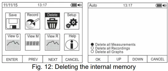
- ഓപ്ഷനുകൾ തിരഞ്ഞെടുക്കാൻ F2 അല്ലെങ്കിൽ F3 കീ ഉപയോഗിക്കുക:
➢ എല്ലാ അളവുകളും ഇല്ലാതാക്കുക → എല്ലാ സ്നാപ്പ്ഷോട്ടുകളും (അളവുകൾ) ഇല്ലാതാക്കി.
➢ എല്ലാ റെക്കോർഡിംഗുകളും ഇല്ലാതാക്കുക → എല്ലാ റെക്കോർഡിംഗുകളും ഇല്ലാതാക്കി
➢ എല്ലാ ഗ്രാഫുകളും ഇല്ലാതാക്കുക → എല്ലാ ഗ്രാഫുകളും ഇല്ലാതാക്കി. - തിരഞ്ഞെടുത്ത പ്രവർത്തനം നടപ്പിലാക്കാൻ F1 (ശരി) കീ അമർത്തുക (ഉപകരണം ഒരു സ്ഥിരീകരണ സന്ദേശം കാണിക്കുന്നു). ഉപകരണത്തിന്റെ പൊതുവായ ക്രമീകരണങ്ങൾ
- "സെറ്റപ്പ്" എന്ന ചിഹ്നം തിരഞ്ഞെടുക്കാൻ F2 അല്ലെങ്കിൽ F3 കീ ഉപയോഗിക്കുക, തുടർന്ന് F1 കീ അമർത്തുക (ചിത്രം 13 കാണുക - ഇടതുവശം).

- ഓപ്ഷനുകൾ തിരഞ്ഞെടുക്കാൻ F2 അല്ലെങ്കിൽ F3 കീ ഉപയോഗിക്കുക:
➢ പുനഃസജ്ജമാക്കുക → ഉപകരണത്തിന്റെ സ്ഥിരസ്ഥിതി അവസ്ഥകൾ പുനഃസ്ഥാപിക്കുന്നു.
➢ ഫോർമാറ്റ് → കീ ടോൺ സജീവമാക്കാൻ അനുവദിക്കുന്നു, തീയതി/സമയത്തിന്റെയും പ്രദർശിപ്പിച്ച സംഖ്യകളുടെയും (ദശാംശ കോമ അല്ലെങ്കിൽ പോയിന്റ്) ഫോർമാറ്റ് സജ്ജമാക്കുന്നു.
➢ പൊതുവായത് → സിസ്റ്റത്തിന്റെ തീയതി/സമയം സജ്ജീകരിക്കാനും, ഓട്ടോ പവർ ഓഫ് ഇടവേള, പശ്ചാത്തല നിറം, ഡിസ്പ്ലേയുടെ ഫോണ്ട് നിറം, തരം എന്നിവ നിർവചിക്കാനും, സിസ്റ്റത്തിന്റെ ഭാഷ തിരഞ്ഞെടുക്കാനും അനുവദിക്കുന്നു.
➢ മീറ്റർ വിവരം → ആന്തരിക ഫേംവെയർ പതിപ്പിനെയും മെമ്മറിയുടെ ലഭ്യമായ സ്ഥലത്തെയും കുറിച്ചുള്ള വിവരങ്ങൾ നൽകുന്നു. - തിരഞ്ഞെടുത്ത പ്രവർത്തനം നടത്താൻ F1 (ENTER) കീ അമർത്തുക അല്ലെങ്കിൽ അളക്കൽ സ്ക്രീനിലേക്ക് തിരികെ പോകാൻ F4 (CANCEL) കീ അമർത്തുക. ഉപകരണത്തിന്റെ പൊതുവായ ക്രമീകരണങ്ങൾ - പുനഃസജ്ജമാക്കുക.

- റീസെറ്റ് സജീവമാക്കാൻ F1 (ശരി) കീ അമർത്തുക.
- പുനഃസജ്ജീകരണ പ്രവർത്തനം ഉപകരണത്തിന്റെ ആന്തരിക മെമ്മറി ഇല്ലാതാക്കുന്നില്ല.
ഉപകരണത്തിന്റെ പൊതുവായ ക്രമീകരണങ്ങൾ - ഫോർമാറ്റ്
- ഓപ്ഷനുകൾ തിരഞ്ഞെടുക്കാൻ F2 അല്ലെങ്കിൽ F3 കീ ഉപയോഗിക്കുക: ➢ കീ ടോൺ → ഫംഗ്ഷൻ കീകളുടെ ടോൺ സജീവമാക്കാനോ നിർജ്ജീവമാക്കാനോ അനുവദിക്കുന്നു.
➢ സംഖ്യാ ഫോർമാറ്റ് → ഓപ്ഷനുകൾക്കിടയിൽ ഡിസ്പ്ലേയിൽ കാണിച്ചിരിക്കുന്ന സംഖ്യകളുടെ ഫോർമാറ്റ് നിർവചിക്കാൻ അനുവദിക്കുന്നു: 0.000 (ദശാംശ പോയിന്റ്), 0,000 (കോമ)
➢ തീയതി ഫോർമാറ്റ് → ഓപ്ഷനുകൾക്കിടയിൽ സിസ്റ്റം തീയതിയുടെ ഫോർമാറ്റ് നിർവചിക്കാൻ അനുവദിക്കുന്നു: MM/DD/YY, DD/MM/YY.
➢ സമയ ഫോർമാറ്റ് → ഓപ്ഷനുകൾക്കിടയിൽ സിസ്റ്റം സമയത്തിന്റെ ഫോർമാറ്റ് നിർവചിക്കാൻ അനുവദിക്കുന്നു: - ഞങ്ങളുടേതും 24 മണിക്കൂറും
- സെറ്റിംഗ്സിനായി F1 (എഡിറ്റ്) കീയും F2, F3 കീകളും ഉപയോഗിക്കുക അല്ലെങ്കിൽ മുമ്പത്തെ സ്ക്രീനിലേക്ക് മടങ്ങാൻ F4 കീ ഉപയോഗിക്കുക. ഉപകരണത്തിന്റെ പൊതുവായ ക്രമീകരണങ്ങൾ - ഡിസ്പ്ലേ

- ഓപ്ഷനുകൾ തിരഞ്ഞെടുക്കാൻ F2 അല്ലെങ്കിൽ F3 കീ ഉപയോഗിക്കുക:
➢ സെറ്റ് ഡേറ്റ് → ഫോർമാറ്റ് മെനുവിൽ നിർവചിച്ചിരിക്കുന്നതുപോലെ സിസ്റ്റത്തിന്റെ തീയതി സജ്ജീകരിക്കാൻ അനുവദിക്കുന്നു.
➢ സമയം സജ്ജമാക്കുക → ഫോർമാറ്റ് മെനുവിൽ നിർവചിച്ചിരിക്കുന്നതുപോലെ സിസ്റ്റത്തിന്റെ സമയം സജ്ജമാക്കാൻ അനുവദിക്കുന്നു.
➢ ഓട്ടോ പവർ ഓഫ് → ശ്രേണിയിൽ ഐഡലിംഗ് ചെയ്യുമ്പോൾ ഉപകരണത്തിന്റെ ഓട്ടോ പവർ ഓഫ് ഇടവേള നിർവചിക്കാൻ അനുവദിക്കുന്നു: 5 മിനിറ്റ് 60 മിനിറ്റ് റെസല്യൂഷൻ 1 മിനിറ്റ്. ഫംഗ്ഷൻ പ്രവർത്തനരഹിതമാക്കാൻ മൂല്യം 00 സജ്ജമാക്കുക. ഉപകരണം യാന്ത്രികമായി ഓഫാക്കിയ ശേഷം വീണ്ടും ഓണാക്കാൻ F3 കീ അമർത്തുക.
➢ ഫോർഗ്രൗണ്ട് → ഡിസ്പ്ലേയുടെ പശ്ചാത്തല നിറവും ഫോണ്ടിന്റെ നിറവും നിർവചിക്കാൻ അനുവദിക്കുന്നു.
➢ ഫോണ്ട് തിരഞ്ഞെടുക്കുക → ലഭ്യമായ ഓപ്ഷനുകളിൽ ഫോണ്ടിന്റെ തരം അല്ലെങ്കിൽ ഡിസ്പ്ലേ നിർവചിക്കാൻ അനുവദിക്കുന്നു (0, 1, 2).
➢ ഭാഷ → ഇറ്റാലിയൻ, ഇംഗ്ലീഷ്, സ്പാനിഷ്, ജർമ്മൻ, ഫ്രഞ്ച് എന്നീ ഓപ്ഷനുകളിൽ നിന്ന് സിസ്റ്റത്തിന്റെ ഭാഷ തിരഞ്ഞെടുക്കാൻ അനുവദിക്കുന്നു.
ഉപകരണത്തിന്റെ പൊതുവായ ക്രമീകരണങ്ങൾ - ഉപകരണ വിവരങ്ങൾ
- ഉപകരണം ഇനിപ്പറയുന്ന വിവരങ്ങൾ കാണിക്കുന്നു:
➢ ഫേംവെയർ പതിപ്പ് → ആന്തരിക ഫേംവെയർ പതിപ്പ്
➢ സൗജന്യ മെമ്മറി → ശതമാനംtagസ്നാപ്പ്ഷോട്ടുകൾ (SAVE), റെക്കോർഡിംഗുകൾ (REC), ഗ്രാഫുകൾ (GRAPH) എന്നിവ സംരക്ഷിക്കുന്നതിനായി മെമ്മറിയിൽ ശേഷിക്കുന്ന സ്വതന്ത്ര സ്ഥലത്തിന്റെ e മൂല്യങ്ങൾ. - മുമ്പത്തെ സ്ക്രീനിലേക്ക് തിരികെ പോകാൻ F4 കീ അമർത്തുക. ഡിസ്പ്ലേയിലേക്ക് ഗ്രാഫുകൾ തിരിച്ചുവിളിക്കുന്നു.

- "" ചിഹ്നം തിരഞ്ഞെടുക്കാൻ F2 അല്ലെങ്കിൽ F3 കീ ഉപയോഗിക്കുക.View G” അമർത്തി F1 കീ അമർത്തുക (ചിത്രം 18 കാണുക – ഇടതുവശം).
- ഉപകരണത്തിന്റെ മെമ്മറിയിൽ സേവ് ചെയ്തിരിക്കുന്നവയിൽ നിന്ന് ആവശ്യമുള്ള ഗ്രാഫ് തിരഞ്ഞെടുക്കാൻ F2 (PREV) അല്ലെങ്കിൽ F3 (NEXT) കീകൾ ഉപയോഗിക്കുക, ഗ്രാഫ് തുറക്കാൻ F1 (ENTER) കീ അമർത്തുക (ചിത്രം 18 കാണുക – മധ്യഭാഗം).
- ഡിസ്പ്ലേയുടെ അടിയിലുള്ള അനുബന്ധ മൂല്യം നിരീക്ഷിച്ചുകൊണ്ട്, ഗ്രാഫിനുള്ളിലെ കഴ്സർ രണ്ട് ദിശകളിലേക്കും നീക്കാൻ F2 (<<) അല്ലെങ്കിൽ F3 (>>) കീകൾ ഉപയോഗിക്കുക (ചിത്രം 18 – വലതുവശത്ത് കാണുക).
- തിരഞ്ഞെടുത്ത ഗ്രാഫ് ഇല്ലാതാക്കാൻ F1 (DELETE) കീ അമർത്തുക അല്ലെങ്കിൽ മുമ്പത്തെ സ്ക്രീനിലേക്ക് തിരികെ പോകാൻ F4 (BACK) കീ അമർത്തുക. ഡിസ്പ്ലേയിൽ അളന്ന ഡാറ്റ (സ്നാപ്പ്ഷോട്ടുകൾ) തിരിച്ചുവിളിക്കുന്നു.

- "" ചിഹ്നം തിരഞ്ഞെടുക്കാൻ F2 അല്ലെങ്കിൽ F3 കീ ഉപയോഗിക്കുക.View M” അമർത്തി F1 കീ അമർത്തുക (ചിത്രം 19 കാണുക – ഇടതുവശം).
- തിരഞ്ഞെടുക്കാൻ F2 (PREV) അല്ലെങ്കിൽ F3 (NEXT) കീ ഉപയോഗിക്കുക, view ഉപകരണത്തിന്റെ മെമ്മറിയിൽ സേവ് ചെയ്തിരിക്കുന്നവയിൽ നിന്ന് ആവശ്യമുള്ള അളവ് (ചിത്രം 19 കാണുക - വലതുവശത്ത്). ഡിസ്പ്ലേയുടെ വലതുവശത്ത് താഴെയായി അളവിന്റെ റഫറൻസ് ദൃശ്യമാകുന്നു.
- തിരഞ്ഞെടുത്ത അളവ് ഇല്ലാതാക്കാൻ F1 (DELETE) കീ അമർത്തുക അല്ലെങ്കിൽ പ്രധാന സ്ക്രീനിലേക്ക് തിരികെ പോകാൻ F4 (CLOSE) കീ അമർത്തുക റെക്കോർഡിംഗുകൾ ഡിസ്പ്ലേയിലേക്ക് തിരിച്ചുവിളിക്കുന്നു.

- "" ചിഹ്നം തിരഞ്ഞെടുക്കാൻ F2 അല്ലെങ്കിൽ F3 കീ ഉപയോഗിക്കുക.View R” കീ അമർത്തി F1 കീ അമർത്തുക (ചിത്രം 20 കാണുക – ഇടതുവശം).
- ഉപകരണത്തിന്റെ മെമ്മറിയിൽ സേവ് ചെയ്തിരിക്കുന്നവയിൽ നിന്ന് ആവശ്യമുള്ള റെക്കോർഡിംഗ് തിരഞ്ഞെടുക്കാൻ F2 (PREV) അല്ലെങ്കിൽ F3 (NEXT) കീ ഉപയോഗിക്കുക (ചിത്രം 20 കാണുക – മധ്യഭാഗം). റെക്കോർഡിംഗ് റഫറൻസ് ഡിസ്പ്ലേയുടെ അടിയിൽ ദൃശ്യമാകും.
- റെക്കോർഡിംഗിന്റെ ട്രെൻഡ് പ്രദർശിപ്പിക്കുന്നതിന് F1 (TREND) കീ അമർത്തുക.
- ഗ്രാഫിൽ കഴ്സർ നീക്കാൻ F3 (>) കീ അമർത്തി ഡിസ്പ്ലേയുടെ അടിയിലുള്ള അനുബന്ധ മൂല്യം നിരീക്ഷിക്കുക.
- ഗ്രാഫിന്റെ സൂമിംഗ് ഫംഗ്ഷൻ സജീവമാക്കാൻ (ലഭ്യമെങ്കിൽ) F2 (+) കീ അമർത്തുക.
- തിരഞ്ഞെടുത്ത റെക്കോർഡിംഗ് ഇല്ലാതാക്കാൻ F1 (DELETE) കീ അമർത്തുക അല്ലെങ്കിൽ മുമ്പത്തെ സ്ക്രീനിലേക്ക് തിരികെ പോകാൻ F4 (BACK) കീ അമർത്തുക.
ഡിസ്പ്ലേയിൽ ഓൺലൈനിൽ സഹായം
- "സഹായം" എന്ന ചിഹ്നം തിരഞ്ഞെടുക്കാൻ F2 അല്ലെങ്കിൽ F3 കീ ഉപയോഗിക്കുക, തുടർന്ന് F1 കീ അമർത്തുക (ചിത്രം 21 കാണുക).
- സന്ദർഭ ഓൺലൈൻ സഹായത്തിന്റെ പേജുകൾ ബ്രൗസ് ചെയ്യാൻ F2 (മുകളിലേക്ക്) അല്ലെങ്കിൽ F3 (താഴേക്ക്) ഉപയോഗിക്കുക.
- പ്രധാന സ്ക്രീനിലേക്ക് തിരികെ പോകാൻ F4 (CLOSE) കീ അമർത്തുക.
പ്രവർത്തന നിർദ്ദേശങ്ങൾ
5.1. ഡിസി, എസി+ഡിസി വോളിയംTAGഇ മെഷർമെൻ്റ്
![]() ജാഗ്രത
ജാഗ്രത
പരമാവധി ഇൻപുട്ട് DC വോളിയംtagഇ 1000V ആണ്. വോളിയം അളക്കരുത്tagഈ മാനുവലിൽ നൽകിയിരിക്കുന്ന പരിധികൾ കവിയുന്നു. വോളിയം കവിയുന്നുtage പരിധികൾ ഉപയോക്താവിന് വൈദ്യുതാഘാതത്തിനും ഉപകരണത്തിന് കേടുപാടുകൾക്കും കാരണമാകും.

- സ്ഥാനങ്ങൾ തിരഞ്ഞെടുക്കുക വി Hz% അല്ലെങ്കിൽ mV
- ഇൻപുട്ട് ടെർമിനലിലേക്ക് ചുവന്ന കേബിൾ ചേർക്കുക ഇൻപുട്ട് ടെർമിനൽ COM-ലേക്കുള്ള ബ്ലാക്ക് കേബിളും.
- അളക്കേണ്ട സർക്യൂട്ടിൻ്റെ പോസിറ്റീവ്, നെഗറ്റീവ് സാധ്യതകളുള്ള പാടുകളിൽ യഥാക്രമം റെഡ് ലെഡ്, ബ്ലാക്ക് ലെഡ് എന്നിവ സ്ഥാപിക്കുക (ചിത്രം 22 കാണുക). ഡിസ്പ്ലേ വോള്യത്തിൻ്റെ മൂല്യം കാണിക്കുന്നുtage.
- ഡിസ്പ്ലേ "OL" എന്ന സന്ദേശം കാണിക്കുകയാണെങ്കിൽ, ഉയർന്ന ശ്രേണി തിരഞ്ഞെടുക്കുക.
- ഉപകരണത്തിന്റെ ഡിസ്പ്ലേയിൽ "-" എന്ന ചിഹ്നം ദൃശ്യമാകുമ്പോൾ, അതിനർത്ഥം വോളിയം എന്നാണ്tagചിത്രം 22-ലെ കണക്ഷനുമായി ബന്ധപ്പെട്ട് e-ന് വിപരീത ദിശയുണ്ട്.
- HOLD, RANGE, REL ഫംഗ്ഷനുകൾ ഉപയോഗിക്കുന്നതിന്, § 4.2 കാണുക.
- AC+DC അളക്കലിനായി, § 4.3.2 കാണുക, ആന്തരിക പ്രവർത്തനങ്ങൾ ഉപയോഗിക്കുന്നതിന്, § 4.3 കാണുക.
5.2 എസി VOLTAGഇ മെഷർമെൻ്റ്
![]() ജാഗ്രത
ജാഗ്രത
പരമാവധി ഇൻപുട്ട് എസി വോള്യംtagഇ 1000V ആണ്. വോളിയം അളക്കരുത്tagഈ മാനുവലിൽ നൽകിയിരിക്കുന്ന പരിധികൾ കവിയുന്നു. വോളിയം കവിയുന്നുtage പരിധികൾ ഉപയോക്താവിന് വൈദ്യുതാഘാതത്തിനും ഉപകരണത്തിന് കേടുപാടുകൾക്കും കാരണമാകും.

- സ്ഥാനങ്ങൾ തിരഞ്ഞെടുക്കുക വി Hz% അല്ലെങ്കിൽ mV
- mV സ്ഥാനത്ത്, F2 (MODE) കീ അമർത്തുക view ഡിസ്പ്ലേയിൽ "~" ചിഹ്നം.
- ഇൻപുട്ട് ടെർമിനലിലേക്ക് ചുവന്ന കേബിൾ ചേർക്കുക
 ഇൻപുട്ട് ടെർമിനൽ COM-ലേക്കുള്ള ബ്ലാക്ക് കേബിളും.
 - അളക്കേണ്ട സർക്യൂട്ടിന്റെ പാടുകളിൽ യഥാക്രമം റെഡ് ലെഡും ബ്ലാക്ക് ലെഡും സ്ഥാപിക്കുക (ചിത്രം 23 കാണുക). ഡിസ്പ്ലേ വോള്യത്തിന്റെ മൂല്യം കാണിക്കുന്നുtage.
- ഡിസ്പ്ലേ "OL" എന്ന സന്ദേശം കാണിക്കുകയാണെങ്കിൽ, ഉയർന്ന ശ്രേണി തിരഞ്ഞെടുക്കുക.
- ഇൻപുട്ട് വോള്യത്തിന്റെ ഫ്രീക്വൻസിയുടെയും ഡ്യൂട്ടി സൈക്കിളിന്റെയും മൂല്യങ്ങൾ പ്രദർശിപ്പിക്കുന്നതിന് “Hz” അല്ലെങ്കിൽ “%” അളവുകൾ തിരഞ്ഞെടുക്കാൻ F2 (MODE) കീ അമർത്തുക.tage. “%” എന്ന ഫംഗ്ഷന്റെ പോസിറ്റീവ് അല്ലെങ്കിൽ നെഗറ്റീവ് ഹാഫ്-വേവ് തിരഞ്ഞെടുക്കാൻ F1(TRIG) കീ അമർത്തുക. ഈ ഫംഗ്ഷനുകളിൽ ബാർഗ്രാഫ് സജീവമല്ല.
- HOLD, RANGE, REL ഫംഗ്ഷനുകൾ ഉപയോഗിക്കുന്നതിന്, § 4.2 കാണുക.
- ആന്തരിക പ്രവർത്തനങ്ങൾ ഉപയോഗിക്കുന്നതിന്, § 4.3 കാണുക.
5.3 AC/DC VOLTAGകുറഞ്ഞ ഇംപെഡൻസുള്ള ഇ മെഷർമെന്റ് (LOZ)
![]() ജാഗ്രത
ജാഗ്രത
പരമാവധി ഇൻപുട്ട് എസി/ഡിസി വോള്യംtagഇ 600V ആണ്. വോളിയം അളക്കരുത്tagഈ മാനുവലിൽ നൽകിയിരിക്കുന്ന പരിധികൾ കവിയുന്നു. വോളിയം കവിയുന്നുtage പരിധികൾ ഉപയോക്താവിന് വൈദ്യുതാഘാതത്തിനും ഉപകരണത്തിന് കേടുപാടുകൾക്കും കാരണമാകും.

- സ്ഥാനം LoZV തിരഞ്ഞെടുക്കുക
 . “LoZ” ഉം “DC” ഉം ചിഹ്നങ്ങൾ കാണിച്ചിരിക്കുന്നു.
 - "AC" അളവ് തിരഞ്ഞെടുക്കാൻ MODE (F2) കീ അമർത്തുക.
- ഇൻപുട്ട് ടെർമിനലിലേക്ക് ചുവന്ന കേബിൾ ചേർക്കുക ഇൻപുട്ട് ടെർമിനൽ COM-ലേക്കുള്ള ബ്ലാക്ക് കേബിളും
- അളക്കേണ്ട സർക്യൂട്ടിന്റെ ആവശ്യമുള്ള സ്ഥലങ്ങളിലോ (ചിത്രം 24 കാണുക) അല്ലെങ്കിൽ അളക്കേണ്ട സർക്യൂട്ടിന്റെ പോസിറ്റീവ്, നെഗറ്റീവ് സാധ്യതകളുള്ള സ്ഥലങ്ങളിലോ യഥാക്രമം റെഡ് ലെഡ്, ബ്ലാക്ക് ലെഡ് എന്നിവ സ്ഥാപിക്കുക (ചിത്രം 22 കാണുക). ഡിസ്പ്ലേ വോള്യത്തിന്റെ മൂല്യം കാണിക്കുന്നുtage.
- "OL" എന്ന സന്ദേശം ഡിസി വോള്യത്തിന്റെ മൂല്യം സൂചിപ്പിക്കുന്നുtage പരമാവധി അളക്കാവുന്ന മൂല്യം കവിയുന്നു.
- ഉപകരണത്തിന്റെ ഡിസ്പ്ലേയിൽ "-" എന്ന ചിഹ്നം ദൃശ്യമാകുമ്പോൾ, അതിനർത്ഥം വോളിയം എന്നാണ്tagചിത്രം 22-ലെ കണക്ഷനുമായി ബന്ധപ്പെട്ട് e-ന് വിപരീത ദിശയുണ്ട്
- HOLD, RANGE, REL ഫംഗ്ഷൻ ഉപയോഗിക്കുന്നതിന്, § 4.2 കാണുക.
- ആന്തരിക പ്രവർത്തനങ്ങൾ ഉപയോഗിക്കുന്നതിന്, § 4.3 കാണുക.
5.4 ഫ്രീക്വൻസിയും ഡ്യൂട്ടി സൈക്കിൾ അളവും
![]() ജാഗ്രത
ജാഗ്രത
പരമാവധി ഇൻപുട്ട് എസി വോള്യംtagഇ 1000V ആണ്. വോളിയം അളക്കരുത്tagഈ മാനുവലിൽ നൽകിയിരിക്കുന്ന പരിധികൾ കവിയുന്നു. വോളിയം കവിയുന്നുtage പരിധികൾ ഉപയോക്താവിന് വൈദ്യുതാഘാതത്തിനും ഉപകരണത്തിന് കേടുപാടുകൾക്കും കാരണമാകും.

1. സ്ഥാനം Hz% തിരഞ്ഞെടുക്കുക.
2. ഇൻപുട്ട് വോള്യത്തിന്റെ ഫ്രീക്വൻസിയുടെയും ഡ്യൂട്ടി സൈക്കിളിന്റെയും മൂല്യങ്ങൾ പ്രദർശിപ്പിക്കുന്നതിന് “Hz” അല്ലെങ്കിൽ “%” അളവുകൾ തിരഞ്ഞെടുക്കാൻ F2 (MODE) കീ അമർത്തുക.tage.
3. ചുവന്ന കേബിൾ ഇൻപുട്ട് ടെർമിനലിലേക്ക് തിരുകുക.![]() ഇൻപുട്ട് ടെർമിനൽ COM-ലേക്കുള്ള ബ്ലാക്ക് കേബിളും.
ഇൻപുട്ട് ടെർമിനൽ COM-ലേക്കുള്ള ബ്ലാക്ക് കേബിളും.
4. അളക്കേണ്ട സർക്യൂട്ടിന്റെ സ്ഥലങ്ങളിൽ യഥാക്രമം ചുവന്ന ലെഡും കറുത്ത ലെഡും സ്ഥാപിക്കുക (ചിത്രം 25 കാണുക). ആവൃത്തിയുടെ (Hz) അല്ലെങ്കിൽ ഡ്യൂട്ടി സൈക്കിളിന്റെ (%) മൂല്യം ഡിസ്പ്ലേയിൽ കാണിച്ചിരിക്കുന്നു. ഈ ഫംഗ്ഷനുകളിൽ ബാർഗ്രാഫ് സജീവമല്ല.
5. HOLD, REL ഫംഗ്ഷൻ ഉപയോഗിക്കുന്നതിന്, § 4.2 കാണുക.
6. ആന്തരിക പ്രവർത്തനങ്ങൾ ഉപയോഗിക്കുന്നതിന്, § 4.3 കാണുക
5.5 റെസിസ്റ്റൻസ് മെഷർമെന്റും കണ്ടിന്യൂറ്റി ടെസ്റ്റും
![]() ജാഗ്രത
ജാഗ്രത
ഏതെങ്കിലും പ്രതിരോധം അളക്കാൻ ശ്രമിക്കുന്നതിന് മുമ്പ്, അളക്കേണ്ട സർക്യൂട്ടിൽ നിന്ന് വൈദ്യുതി വിതരണം വിച്ഛേദിക്കുകയും എല്ലാ കപ്പാസിറ്ററുകളും ഡിസ്ചാർജ് ചെയ്തിട്ടുണ്ടെന്ന് ഉറപ്പാക്കുകയും ചെയ്യുക.

- സ്ഥാനം തിരഞ്ഞെടുക്കുക

- ഇൻപുട്ട് ടെർമിനലിലേക്ക് ചുവന്ന കേബിൾ ചേർക്കുക ഇൻപുട്ട് ടെർമിനൽ COM-ലേക്കുള്ള ബ്ലാക്ക് കേബിളും.
- അളക്കേണ്ട സർക്യൂട്ടിന്റെ ആവശ്യമുള്ള സ്ഥലങ്ങളിൽ ടെസ്റ്റ് ലീഡുകൾ സ്ഥാപിക്കുക (ചിത്രം 26 കാണുക). ഡിസ്പ്ലേ പ്രതിരോധത്തിന്റെ മൂല്യം കാണിക്കുന്നു.
- ഡിസ്പ്ലേ "OL" എന്ന സന്ദേശം കാണിക്കുകയാണെങ്കിൽ, ഉയർന്ന ശ്രേണി തിരഞ്ഞെടുക്കുക.
- കണ്ടിന്യുറ്റി ടെസ്റ്റുമായി ബന്ധപ്പെട്ട അളവ് )))” തിരഞ്ഞെടുക്കാൻ F2 (MODO) കീ അമർത്തുക, തുടർന്ന് അളക്കേണ്ട സർക്യൂട്ടിലെ ആവശ്യമുള്ള സ്ഥലങ്ങളിൽ ടെസ്റ്റ് ലീഡുകൾ സ്ഥാപിക്കുക.
- പ്രതിരോധത്തിന്റെ മൂല്യം (ഇത് സൂചകം മാത്രമാണ്) 2-ൽ പ്രദർശിപ്പിക്കുകയും പ്രതിരോധത്തിന്റെ മൂല്യം <50Ω ആണെങ്കിൽ ഉപകരണം മുഴങ്ങുകയും ചെയ്യുന്നു.
- HOLD, RANGE, REL ഫംഗ്ഷനുകൾ ഉപയോഗിക്കുന്നതിന്, § 4.2 കാണുക.
- ആന്തരിക പ്രവർത്തനങ്ങൾ ഉപയോഗിക്കുന്നതിന്, § 4.3 കാണുക.
5.6 ഡയോഡ് ടെസ്റ്റ്
![]() ജാഗ്രത
ജാഗ്രത
ഏതെങ്കിലും പ്രതിരോധം അളക്കാൻ ശ്രമിക്കുന്നതിന് മുമ്പ്, അളക്കേണ്ട സർക്യൂട്ടിൽ നിന്ന് വൈദ്യുതി വിതരണം വിച്ഛേദിക്കുകയും എല്ലാ കപ്പാസിറ്ററുകളും ഡിസ്ചാർജ് ചെയ്തിട്ടുണ്ടെന്ന് ഉറപ്പാക്കുകയും ചെയ്യുക.

- സ്ഥാനം തിരഞ്ഞെടുക്കുക
- "+" അളവ് തിരഞ്ഞെടുക്കാൻ F2 (MODE) കീ അമർത്തുക.
- ഇൻപുട്ട് ടെർമിനലിലേക്ക് ചുവന്ന കേബിൾ ചേർക്കുക ഇൻപുട്ട് ടെർമിനൽ COM-ലേക്കുള്ള ബ്ലാക്ക് കേബിളും.
- ടെസ്റ്റ് ചെയ്യേണ്ട ഡയോഡിന്റെ അറ്റത്ത് ലീഡുകൾ സ്ഥാപിക്കുക (ചിത്രം 27 കാണുക), സൂചിപ്പിച്ച പോളാരിറ്റിയെ മാനിക്കുക. നേരിട്ട് ധ്രുവീകരിക്കപ്പെട്ട ത്രെഷോൾഡ് വോള്യത്തിന്റെ മൂല്യംtage ഡിസ്പ്ലേയിൽ കാണിച്ചിരിക്കുന്നു.
- ത്രെഷോൾഡ് മൂല്യം OmV ന് തുല്യമാണെങ്കിൽ, ഡയോഡിന്റെ PN ജംഗ്ഷൻ ഷോർട്ട് സർക്യൂട്ട് ആണ്.
- ഡിസ്പ്ലേ "OL" എന്ന സന്ദേശം കാണിക്കുന്നുവെങ്കിൽ, ചിത്രം 27-ൽ നൽകിയിരിക്കുന്ന സൂചനയുമായി ബന്ധപ്പെട്ട് ഡയോഡിന്റെ ടെർമിനലുകൾ വിപരീതമാണ് അല്ലെങ്കിൽ ഡയോഡിന്റെ PN ജംഗ്ഷൻ തകരാറിലാകുന്നു.
- HOLD, REL ഫംഗ്ഷൻ ഉപയോഗിക്കുന്നതിന്, § 4.2 കാണുക.
- ആന്തരിക പ്രവർത്തനങ്ങൾ ഉപയോഗിക്കുന്നതിന്, § 4.3 കാണുക.
5.7 കപ്പാസിറ്റൻസ് മെഷർമെന്റ്
![]() ജാഗ്രത
ജാഗ്രത
സർക്യൂട്ടുകളിലോ കപ്പാസിറ്ററുകളിലോ കപ്പാസിറ്റൻസ് അളക്കുന്നതിന് മുമ്പ്, പരീക്ഷിക്കുന്ന സർക്യൂട്ടിൽ നിന്നുള്ള വൈദ്യുതി വിതരണം വിച്ഛേദിക്കുകയും അതിലെ എല്ലാ കപ്പാസിറ്റൻസും ഡിസ്ചാർജ് ചെയ്യട്ടെ. മൾട്ടിമീറ്ററും അളക്കേണ്ട കപ്പാസിറ്റൻസും ബന്ധിപ്പിക്കുമ്പോൾ, ശരിയായ പോളാരിറ്റി (ആവശ്യമുള്ളപ്പോൾ) മാനിക്കുക.

- സ്ഥാനം തിരഞ്ഞെടുക്കുക
- "nF" എന്ന ചിഹ്നം ദൃശ്യമാകുന്നതുവരെ F2 (MODE) കീ അമർത്തുക.
- ഇൻപുട്ട് ടെർമിനലിലേക്ക് ചുവന്ന കേബിൾ ചേർക്കുക ഇൻപുട്ട് ടെർമിനൽ COM-ലേക്കുള്ള ബ്ലാക്ക് കേബിളും.
- അളവുകൾ എടുക്കുന്നതിന് മുമ്പ് REL/A കീ അമർത്തുക.
- പരിശോധിക്കേണ്ട കപ്പാസിറ്ററിന്റെ അറ്റത്ത് ലീഡുകൾ സ്ഥാപിക്കുക, ആവശ്യമെങ്കിൽ, പോസിറ്റീവ് (ചുവപ്പ് കേബിൾ), നെഗറ്റീവ് (കറുത്ത കേബിൾ) പോളാരിറ്റി എന്നിവയെ മാനിക്കുക (ചിത്രം 28 കാണുക). ഡിസ്പ്ലേ മൂല്യം കാണിക്കുന്നു. കപ്പാസിറ്റൻസിനെ ആശ്രയിച്ച്, ശരിയായ അന്തിമ മൂല്യം പ്രദർശിപ്പിക്കുന്നതിന് മുമ്പ് ഉപകരണത്തിന് ഏകദേശം 20 സെക്കൻഡ് എടുക്കാം. ഈ ഫംഗ്ഷനിൽ ബാർഗ്രാഫ് സജീവമല്ല.
- കപ്പാസിറ്റൻസിന്റെ മൂല്യം പരമാവധി അളക്കാവുന്ന മൂല്യത്തെ കവിയുന്നുവെന്ന് "OL" എന്ന സന്ദേശം സൂചിപ്പിക്കുന്നു.
- HOLD, REL ഫംഗ്ഷൻ ഉപയോഗിക്കുന്നതിന്, § 4.2 കാണുക.
- ആന്തരിക പ്രവർത്തനങ്ങൾ ഉപയോഗിക്കുന്നതിന്, § 4.3 കാണുക.
5.8 കെ-ടൈപ്പ് പ്രോബ് ഉപയോഗിച്ചുള്ള താപനില അളക്കൽ
![]() ജാഗ്രത
ജാഗ്രത
ഏതെങ്കിലും താപനില അളക്കാൻ ശ്രമിക്കുന്നതിന് മുമ്പ്, അളക്കേണ്ട സർക്യൂട്ടിൽ നിന്ന് വൈദ്യുതി വിതരണം വിച്ഛേദിക്കുകയും എല്ലാ കപ്പാസിറ്ററുകളും ഡിസ്ചാർജ് ചെയ്തിട്ടുണ്ടെന്ന് ഉറപ്പാക്കുകയും ചെയ്യുക.

- സ്ഥാനം തിരഞ്ഞെടുക്കുക

- "°C" അല്ലെങ്കിൽ "F" ചിഹ്നം ദൃശ്യമാകുന്നതുവരെ F2 (MODE) കീ അമർത്തുക.
- നൽകിയിരിക്കുന്ന അഡാപ്റ്റർ ഇൻപുട്ട് ടെർമിനലുകളിലേക്ക് ചേർക്കുക (പോളാർറ്റി +), COM (പോളാരിറ്റി -) (ചിത്രം 29 കാണുക)
- നൽകിയിരിക്കുന്ന കെ-ടൈപ്പ് വയർ പ്രോബ് അല്ലെങ്കിൽ ഓപ്ഷണൽ കെ-ടൈപ്പ് തെർമോകപ്പിൾ (§ 7.2.2 കാണുക) അഡാപ്റ്റർ വഴി ഉപകരണവുമായി ബന്ധിപ്പിക്കുക, അതിലെ പോസിറ്റീവ്, നെഗറ്റീവ് പോളാരിറ്റി എന്നിവയെ മാനിക്കുക. ഡിസ്പ്ലേ താപനിലയുടെ മൂല്യം കാണിക്കുന്നു. ഈ ഫംഗ്ഷനിൽ ബാർഗ്രാഫ് സജീവമല്ല.
- "OL" എന്ന സന്ദേശം താപനിലയുടെ മൂല്യം പരമാവധി അളക്കാവുന്ന മൂല്യത്തേക്കാൾ കൂടുതലാണെന്ന് സൂചിപ്പിക്കുന്നു.
- HOLD, REL ഫംഗ്ഷൻ ഉപയോഗിക്കുന്നതിന്, § 4.2 കാണുക.
- ആന്തരിക പ്രവർത്തനങ്ങൾ ഉപയോഗിക്കുന്നതിന്, § 4.3 കാണുക.
5.9. ഡിസി, എസി+ഡിസി കറന്റ് മെഷർമെന്റും ഇ 4-20MA% റീഡിംഗും
![]() ജാഗ്രത
ജാഗ്രത
പരമാവധി ഇൻപുട്ട് ഡിസി കറന്റ് 10A (ഇൻപുട്ട് 10A) അല്ലെങ്കിൽ 600mA (ഇൻപുട്ട് mAuA) ആണ്. ഈ മാനുവലിൽ നൽകിയിരിക്കുന്ന പരിധികൾ കവിയുന്ന വൈദ്യുതധാരകൾ അളക്കരുത്. വോളിയം കവിയുന്നുtage പരിധികൾ ഉപയോക്താവിന് വൈദ്യുതാഘാതത്തിനും ഉപകരണത്തിന് കേടുപാടുകൾക്കും കാരണമാകും.

- അളക്കേണ്ട സർക്യൂട്ടിൽ നിന്ന് വൈദ്യുതി വിതരണം വിച്ഛേദിക്കുക.
- സ്ഥാനം തിരഞ്ഞെടുക്കുക µA, എം.എ അല്ലെങ്കിൽ 10A 20mA 4-20mA ന്
 വായന. ഡിസി കറന്റ് അല്ലെങ്കിൽ അതേ സ്ഥാനം അളക്കാൻ 4-
 - ചുവന്ന കേബിൾ ഇൻപുട്ട് ടെർമിനൽ 10A യിലോ ഇൻപുട്ട് ടെർമിനൽ mAµA യിലോ തിരുകുക, കറുത്ത കേബിൾ ഇൻപുട്ട് ടെർമിനൽ COM ലേക്ക് തിരുകുക.
- ധ്രുവീയതയെയും നിലവിലെ ദിശയെയും മാനിച്ച് നിങ്ങൾ അളക്കാൻ ആഗ്രഹിക്കുന്ന സർക്യൂട്ടിലേക്ക് റെഡ് ലെഡും ബ്ലാക്ക് ലെഡും ബന്ധിപ്പിക്കുക (ചിത്രം 30 കാണുക).
- അളക്കേണ്ട സർക്യൂട്ട് വിതരണം ചെയ്യുക.
- ഡിസി കറന്റ് മൂല്യം (ചിത്രം 30 കാണുക - ഇടത് വശം) ഡിസ്പ്ലേയിൽ ദൃശ്യമാകുന്നു.
- ഡിസ്പ്ലേയിൽ 4-20mA% (0mA = -25%, 4mA = 0%, 20mA = 100% and 24mA = 125%) എന്ന റീഡിംഗ് മൂല്യം (ചിത്രം 30 വലതുവശത്ത് കാണുക) ദൃശ്യമാകുന്നു. ഈ ഫംഗ്ഷനിൽ ബാർഗ്രാഫ് സജീവമല്ല.
- ഡിസ്പ്ലേ "OL" എന്ന സന്ദേശം കാണിക്കുന്നുവെങ്കിൽ, അളക്കാവുന്ന പരമാവധി മൂല്യം എത്തിയിരിക്കുന്നു.
- ഉപകരണത്തിന്റെ ഡിസ്പ്ലേയിൽ "-" എന്ന ചിഹ്നം ദൃശ്യമാകുമ്പോൾ, ചിത്രം 30-ലെ കണക്ഷനുമായി ബന്ധപ്പെട്ട് കറന്റിന് വിപരീത ദിശയുണ്ടെന്ന് അർത്ഥമാക്കുന്നു.
- HOLD, RANGE, REL ഫംഗ്ഷനുകൾ ഉപയോഗിക്കുന്നതിന്, § 4.2 കാണുക.
- AC+DC അളക്കലിനായി, § 4.3.2 കാണുക, ആന്തരിക പ്രവർത്തനങ്ങൾ ഉപയോഗിക്കുന്നതിന്, § 4.3 കാണുക.
5.10 എസി കറൻ്റ് മെഷർമെൻ്റ്
![]() ജാഗ്രത
ജാഗ്രത
പരമാവധി ഇൻപുട്ട് എസി കറന്റ് 10A (ഇൻപുട്ട് 10A) അല്ലെങ്കിൽ 600mA (ഇൻപുട്ട് mAuA) ആണ്. ഈ മാനുവലിൽ നൽകിയിരിക്കുന്ന പരിധികൾ കവിയുന്ന വൈദ്യുതധാരകൾ അളക്കരുത്. വോളിയം കവിയുന്നുtage പരിധികൾ ഉപയോക്താവിന് വൈദ്യുതാഘാതത്തിനും ഉപകരണത്തിന് കേടുപാടുകൾക്കും കാരണമാകും.

- അളക്കേണ്ട സർക്യൂട്ടിൽ നിന്ന് വൈദ്യുതി വിതരണം വിച്ഛേദിക്കുക.
- സ്ഥാനങ്ങൾ തിരഞ്ഞെടുക്കുക μΑ, mA അല്ലെങ്കിൽ 10A
- "AC" അളവ് തിരഞ്ഞെടുക്കാൻ F2 (MODE) കീ അമർത്തുക.
- ചുവന്ന കേബിൾ ഇൻപുട്ട് ടെർമിനൽ 10A യിലോ ഇൻപുട്ട് ടെർമിനൽ mAµA യിലോ തിരുകുക, കറുത്ത കേബിൾ ഇൻപുട്ട് ടെർമിനൽ COM ലേക്ക് തിരുകുക.
- ചുവന്ന ലെഡും കറുത്ത ലെഡും ശ്രേണിയിൽ നിങ്ങൾ അളക്കാൻ ആഗ്രഹിക്കുന്ന സർക്യൂട്ടിലേക്ക് ബന്ധിപ്പിക്കുക (ചിത്രം 31 കാണുക).
- അളക്കേണ്ട സർക്യൂട്ട് വിതരണം ചെയ്യുക. ഡിസ്പ്ലേ നിലവിലെ മൂല്യം കാണിക്കുന്നു.
- ഡിസ്പ്ലേ "OL" എന്ന സന്ദേശം കാണിക്കുന്നുവെങ്കിൽ, അളക്കാവുന്ന പരമാവധി മൂല്യം എത്തിയിരിക്കുന്നു.
- HOLD, RANGE, REL ഫംഗ്ഷനുകൾ ഉപയോഗിക്കുന്നതിന്, § 4.2 കാണുക.
- ആന്തരിക പ്രവർത്തനങ്ങൾ ഉപയോഗിക്കുന്നതിന്, § 4.3 കാണുക.
5.11. ട്രാൻസ്ഡ്യൂസർ CL ഉപയോഗിച്ചുള്ള DC, AC, AC+DC കറന്റ് മെഷർമെന്റ്AMPS
![]() ജാഗ്രത
ജാഗ്രത
- ഈ ഫംഗ്ഷനിലെ പരമാവധി കറന്റ് മെഷർമെന്റ് 3000A AC അല്ലെങ്കിൽ 1000A DC ആണ്. ഈ മാനുവലിൽ നൽകിയിരിക്കുന്ന പരിധികൾ കവിയുന്ന വൈദ്യുതധാരകൾ അളക്കരുത്
- ഫ്ലെക്സിബിൾ ട്രാൻസ്ഡ്യൂസർ cl ഉപയോഗിച്ചാണ് ഉപകരണം അളക്കുന്നത്amp (ഓപ്ഷണൽ ആക്സസറി F3000U) മറ്റ് സ്റ്റാൻഡേർഡ് clamp HT കുടുംബത്തിന്റെ ട്രാൻസ്ഡ്യൂസറുകൾ. ട്രാൻസ്ഡ്യൂസർ clampകണക്ഷൻ നടത്തുന്നതിന് HT ഔട്ട്പുട്ട് കണക്ടറുള്ള NOCANBA ഓപ്ഷണൽ അഡാപ്റ്റർ ആവശ്യമാണ്.

- സ്ഥാനം തിരഞ്ഞെടുക്കുക

- “AC”, “DC” അല്ലെങ്കിൽ “AC+DC” അളവ് തിരഞ്ഞെടുക്കാൻ F2(MODE) കീ അമർത്തുക.
- ഇൻസ്ട്രുമെന്റിൽ തിരഞ്ഞെടുക്കാൻ RANGE കീ അമർത്തുക, ട്രാൻസ്ഡ്യൂസർ cl-ൽ സജ്ജീകരിച്ചിരിക്കുന്ന അതേ ശ്രേണിamp ഓപ്ഷനുകളിൽ: 1000mA, 10A, 30A, 40A (HT4006-ന് മാത്രം) 100A, 300A, 400A (HT4006-ന് മാത്രം), 1000A, 3000A. തിരഞ്ഞെടുത്ത ശ്രേണി ഡിസ്പ്ലേയുടെ മുകളിൽ ഇടത് ഭാഗത്ത് ദൃശ്യമാകും.
- ഇൻപുട്ട് ടെർമിനലിലേക്ക് ചുവന്ന കേബിൾ ചേർക്കുക ഇൻപുട്ട് ടെർമിനലായ COM-ലേക്ക് ബ്ലാക്ക് കേബിളും. HT കണക്ടറുള്ള മറ്റ് സ്റ്റാൻഡേർഡ് ട്രാൻസ്ഡ്യൂസറുകൾക്ക് (§ കാണുക) NOCANBA ഓപ്ഷണൽ ആക്സസറി ഉപയോഗിക്കുക. ട്രാൻസ്ഡ്യൂസർ cl-ന്റെ ഉപയോഗത്തെക്കുറിച്ചുള്ള വിവരങ്ങൾക്ക്ampആപേക്ഷിക ഉപയോക്തൃ മാനുവൽ സൂചിപ്പിക്കുന്നു
- താടിയെല്ലിനുള്ളിൽ കേബിൾ തിരുകുക (ചിത്രം 32 കാണുക). നിലവിലെ മൂല്യം ഡിസ്പ്ലേയിൽ ദൃശ്യമാകുന്നു
- ഡിസ്പ്ലേ "OL" എന്ന സന്ദേശം കാണിക്കുന്നുവെങ്കിൽ, പരമാവധി അളക്കാവുന്ന മൂല്യം എത്തിയിരിക്കുന്നു
- HOLD, RANGE, REL ഫംഗ്ഷനുകൾ ഉപയോഗിക്കുന്നതിന്, § 4.2 കാണുക
- ആന്തരിക പ്രവർത്തനങ്ങൾ ഉപയോഗിക്കുന്നതിന്, § 4.3 കാണുക.
മെയിൻറനൻസ്
![]() ജാഗ്രത
ജാഗ്രത
- വിദഗ്ധരും പരിശീലനം ലഭിച്ച സാങ്കേതിക വിദഗ്ധരും മാത്രമേ അറ്റകുറ്റപ്പണികൾ നടത്താവൂ. അറ്റകുറ്റപ്പണികൾ നടത്തുന്നതിന് മുമ്പ്, ഇൻപുട്ട് ടെർമിനലുകളിൽ നിന്ന് എല്ലാ കേബിളുകളും വിച്ഛേദിക്കുക.
- ഉയർന്ന ആർദ്രതയോ ഉയർന്ന താപനിലയോ ഉള്ള അന്തരീക്ഷത്തിൽ ഉപകരണം ഉപയോഗിക്കരുത്. നേരിട്ട് സൂര്യപ്രകാശം ഏൽക്കരുത്.
- ഉപയോഗത്തിന് ശേഷം എല്ലായ്പ്പോഴും ഉപകരണം സ്വിച്ച് ഓഫ് ചെയ്യുക. ഉപകരണം ദീർഘനേരം ഉപയോഗിക്കാൻ പാടില്ലെങ്കിൽ, ഉപകരണത്തിന്റെ ആന്തരിക സർക്യൂട്ടുകളെ തകരാറിലാക്കുന്ന ദ്രാവക ചോർച്ച ഒഴിവാക്കാൻ ബാറ്ററി നീക്കം ചെയ്യുക.
6.1. ആന്തരിക ബാറ്ററി റീചാർജ് ചെയ്യുന്നു
LCD ചിഹ്നം പ്രദർശിപ്പിക്കുമ്പോൾ " ![]() ”, ആന്തരിക ബാറ്ററി റീചാർജ് ചെയ്യേണ്ടത് ആവശ്യമാണ്.
”, ആന്തരിക ബാറ്ററി റീചാർജ് ചെയ്യേണ്ടത് ആവശ്യമാണ്.

- റോട്ടറി സ്വിച്ച് ഓഫ് ആക്കി ഇൻപുട്ട് ടെർമിനലുകളിൽ നിന്ന് കേബിളുകൾ നീക്കം ചെയ്യുക.
- ബാറ്ററി ചാർജർ പവർ സപ്ലൈയുടെ അഡാപ്റ്റർ ഉപകരണത്തിലേക്ക്, നാല് ഇൻപുട്ട് ടെർമിനലുകളിലേക്ക് തിരുകുക (ചിത്രം 33 കാണുക).
- പവർ സപ്ലൈയുടെ കണക്റ്റർ അഡാപ്റ്ററിലേക്ക് തിരുകുക, പവർ സപ്ലൈ ഇലക്ട്രിക് മെയിനുമായി ബന്ധിപ്പിക്കുക.
- ഡിസ്പ്ലേയിൽ പച്ച ബാറ്ററി മിന്നിമറയുന്നതിന്റെ ഒരു ചിഹ്നം ദൃശ്യമാകുന്നു. ചിഹ്നം സ്ഥിരമാകുമ്പോൾ റീചാർജ് പ്രക്രിയ പൂർത്തിയാകും.
- പ്രവർത്തനം പൂർത്തിയാകുമ്പോൾ ഉപകരണത്തിൽ നിന്ന് ബാറ്ററി ചാർജർ വിച്ഛേദിക്കുക.
 ജാഗ്രത
ചാർജിംഗ് പ്രക്രിയ പ്രവർത്തിക്കുന്നില്ലെങ്കിൽ, F800mA/1000V പ്രൊട്ടക്ഷൻ ഫ്യൂസിന്റെ സമഗ്രത പരിശോധിക്കുക (§ 7.1.2 കാണുക) ആവശ്യമെങ്കിൽ അത് മാറ്റിസ്ഥാപിക്കുക (§ 6.2 കാണുക)
6.2. ആന്തരിക ഫ്യൂസുകളുടെ മാറ്റിസ്ഥാപിക്കൽ

- റോട്ടറി സ്വിച്ച് ഓഫ് ആക്കി ഇൻപുട്ട് ടെർമിനലുകളിൽ നിന്ന് കേബിളുകൾ നീക്കം ചെയ്യുക.
- ബാറ്ററി കമ്പാർട്ട്മെന്റ് കവറിന്റെ ഫാസ്റ്റണിംഗ് സ്ക്രൂ സ്ഥാനത്ത് നിന്ന് തിരിക്കുക
 അത് നീക്കം ചെയ്യുക (ചിത്രം 34 കാണുക)
 സ്ഥാനത്തേക്ക്
 - കേടായ ഫ്യൂസ് നീക്കം ചെയ്ത് അതേ തരത്തിലുള്ള ഒരു പുതിയ ഫ്യൂസ് ചേർക്കുക (§ 7.1.2 കാണുക).
- ബാറ്ററി കമ്പാർട്ട്മെന്റ് കവർ പുനഃസ്ഥാപിക്കുക, ഫാസ്റ്റണിംഗ് സ്ക്രൂ സ്ഥാനത്ത് നിന്ന് തിരിക്കുക. സ്ഥാനത്തേക്ക് .
6.3 ഉപകരണം വൃത്തിയാക്കുന്നു
ഉപകരണം വൃത്തിയാക്കാൻ മൃദുവായതും ഉണങ്ങിയതുമായ തുണി ഉപയോഗിക്കുക. നനഞ്ഞ തുണികൾ, ലായകങ്ങൾ, വെള്ളം മുതലായവ ഉപയോഗിക്കരുത്.
6.4 ജീവിതാവസാനം
![]() മുന്നറിയിപ്പ്: ഉപകരണത്തിലെ ചിഹ്നം സൂചിപ്പിക്കുന്നത് ഉപകരണവും അതിന്റെ അനുബന്ധ ഉപകരണങ്ങളും വെവ്വേറെ ശേഖരിക്കുകയും ശരിയായി നീക്കം ചെയ്യുകയും വേണം.
മുന്നറിയിപ്പ്: ഉപകരണത്തിലെ ചിഹ്നം സൂചിപ്പിക്കുന്നത് ഉപകരണവും അതിന്റെ അനുബന്ധ ഉപകരണങ്ങളും വെവ്വേറെ ശേഖരിക്കുകയും ശരിയായി നീക്കം ചെയ്യുകയും വേണം.
സാങ്കേതിക സ്പെസിഫിക്കേഷനുകൾ
7.1 സാങ്കേതിക സ്വഭാവസവിശേഷതകൾ
18°C 28°C <75%HR താപനിലയിൽ [%വായന + (അക്കങ്ങളുടെ എണ്ണം*റെസല്യൂഷൻ)] ആയി കൃത്യത കണക്കാക്കുന്നു.
ഡിസി വോളിയംtage
| പരിധി | റെസലൂഷൻ | കൃത്യത | ഇൻപുട്ട് പ്രതിരോധം | അമിത ചാർജിനെതിരെയുള്ള സംരക്ഷണം |
| 600.0 മി | 0.1 മി | ± (0.1% വായന + 5 അക്കങ്ങൾ) | >10 മെഗാവാട്ട് | 1000VDC/ACrms |
| 6.000V | 0.001V | |||
| 60.00V | 0.01V | |||
| 600.0V | 0.1V | ± (0.2% വായന + 5 അക്കങ്ങൾ) | ||
| 1000V | 1V |
AC TRMS വോളിയംtage
| പരിധി | റെസലൂഷൻ | കൃത്യത (*) | അമിത ചാർജിനെതിരെയുള്ള സംരക്ഷണം | |
| (50Hz¸60Hz) | (61Hz¸1kHz) | |||
| 600.0 മി | 0.1 മി | ± (0.9% വായന + 5 അക്കങ്ങൾ) | ± (3.0% റീഡിംഗ് + 5dgt) | 1000VDC/ACrms |
| 6.000V | 0.001V | |||
| 60.00V | 0.01V | |||
| 600.0V | 0.1V | |||
| 1000V | 1V | |||
(*) അളക്കൽ ശ്രേണിയുടെ 10% മുതൽ 100% വരെ കൃത്യത വ്യക്തമാക്കിയിരിക്കുന്നു, ഇൻപുട്ട് ഇംപെഡൻസ്: > 9M ;
കൃത്യത പീക്ക് ഫംഗ്ഷൻ: ±(10%rdg + 30dgt), പീക്ക് പ്രതികരണ സമയം: 1ms
സൈനസോയ്ഡൽ അല്ലാത്ത തരംഗരൂപങ്ങൾക്ക് കൃത്യത: (10.0%വായന + 10dgt)
AC+ DC TRMS വോളിയംtage
| പരിധി | റെസലൂഷൻ | കൃത്യത (*) (50Hz¸1kHz) | ഇൻപുട്ട് പ്രതിരോധം | അമിത ചാർജിനെതിരെയുള്ള സംരക്ഷണം |
| 6.000V | 0.001V | ± (3.0% റീഡിംഗ് + 20dgt) | >10 മെഗാവാട്ട് | 1000VDC/ACrms |
| 60.00V | 0.01V | |||
| 600.0V | 0.1V | |||
| 1000V | 1V |
(*) അളക്കുന്ന ശ്രേണിയുടെ 10% മുതൽ 100% വരെ കൃത്യത വ്യക്തമാക്കിയിരിക്കുന്നു
സൈനസോയ്ഡൽ അല്ലാത്ത തരംഗരൂപങ്ങൾക്ക് കൃത്യത: (10.0%വായന + 10dgt)
DC/AC TRMS വോളിയംtage കുറഞ്ഞ പ്രതിരോധശേഷിയുള്ള (LoZ)
| പരിധി | റെസലൂഷൻ | കൃത്യത (*) (50Hz¸1kHz) | ഇൻപുട്ട് പ്രതിരോധം | അമിത ചാർജിനെതിരെയുള്ള സംരക്ഷണം |
| 6.000V | 0.001V | ± (3.0% വായന+40dgt) | ഏകദേശം 3kW | 600VDC/ACrms |
| 60.00V | 0.01V | |||
| 600.0V | 0.1V | |||
| 600V | 1V |
(*) അളക്കുന്ന ശ്രേണിയുടെ 10% മുതൽ 100% വരെ കൃത്യത വ്യക്തമാക്കിയിരിക്കുന്നു
സൈനസോയ്ഡൽ അല്ലാത്ത തരംഗരൂപങ്ങൾക്ക് കൃത്യത: (10.0%വായന + 10dgt)
ഡിസി കറൻ്റ്
| പരിധി | റെസലൂഷൻ | കൃത്യത | സംരക്ഷണം എതിരായി അമിത ചാർജ് |
| 600.0mA | 0.1mA | ± (0.9% വായന + 5 അക്കങ്ങൾ) | ദ്രുത ഫ്യൂസ് 800mA/1000V |
| 6000mA | 1mA | ||
| 60.00mA | 0.01mA | ||
| 600.0mA | 0.1mA | ± (0.9% വായന + 8 അക്കങ്ങൾ) | |
| 10.00എ | 0.01എ | ± (1.5% വായന + 8 അക്കങ്ങൾ) | ദ്രുത ഫ്യൂസ് 10A/1000V |
AC TRMS കറന്റ്
| പരിധി | റെസലൂഷൻ | കൃത്യത (*) (50Hz¸1kHz) | സംരക്ഷണം എതിരായി അമിത ചാർജ് |
| 600.0mA | 0.1mA | ± (1.2% വായന + 5 അക്കങ്ങൾ) | ദ്രുത ഫ്യൂസ് 800mA/1000V |
| 6000mA | 1mA | ||
| 60.00mA | 0.01mA | ||
| 600.0mA | 0.1mA | ||
| 10.00എ | 0.01എ | ± (1.5% വായന + 5 അക്കങ്ങൾ) | ദ്രുത ഫ്യൂസ് 10A/1000V |
(*) അളക്കൽ ശ്രേണിയുടെ 5% മുതൽ 100% വരെ കൃത്യത വ്യക്തമാക്കിയിരിക്കുന്നു; സൈനസോയ്ഡൽ അല്ലാത്ത തരംഗരൂപങ്ങൾക്ക് കൃത്യത: +(10.0%വായന + 10dgt)
കൃത്യത പീക്ക് ഫംഗ്ഷൻ: ±(10%rdg+30dgt) , AC+DC TRMS കറന്റ്: കൃത്യത (50Hz+1kHz): +(3.0%വായന + 20dgt)
ട്രാൻസ്ഡ്യൂസർ cl ഉള്ള DC കറന്റ്amp
| പരിധി | ഔട്ട്പുട്ട് അനുപാതം | റെസലൂഷൻ | കൃത്യത (*) | സംരക്ഷണം എതിരായി അമിത ചാർജ് |
| 1000mA | 1V/1A | 1mA | ± (1.5%rdg+ 6dgt) | 1000VDC/ACrms |
| 10എ | 100mV/1A | 0.01എ | ||
| 30എ | ||||
| 40A (**) | 10mV/1A | ±(1.5% വാർഷിക ഗ്രാം+26 ദിവസം) (***) | ||
| 100എ |
0.1എ |
± (1.5%rdg+ 6dgt) | ||
| 300എ | ||||
| 400A (**) | 1mV/1A | ±(1.5% വാർഷിക ഗ്രാം+26 ദിവസം) (***) | ||
| 1000എ | 1mV/1A | 1A | ±(1.5%rdg+6dgt) | |
| 3000എ |
(*) ട്രാൻസ്ഡ്യൂസർ ഇല്ലാത്ത ഉപകരണത്തിന് മാത്രമേ കൃത്യത പരാമർശിക്കൂ; (**) HT4006 ട്രാൻസ്ഡ്യൂസർ cl ഉപയോഗിച്ച്amp ; (***) കൃത്യതാ ഉപകരണം + clamp
ട്രാൻസ്ഡ്യൂസർ cl ഉള്ള AC TRMS കറന്റ്amp
| പരിധി | ഔട്ട്പുട്ട് അനുപാതം | റെസലൂഷൻ | കൃത്യത (*) (50Hz¸1kHz) | അമിത ചാർജിനെതിരെയുള്ള സംരക്ഷണം |
| 1000mA | 1V/1A | 1mA | ± (2.5%rdg + 10dgt) | 1000VDC/ACrms |
| 10എ | 100mV/1A | 0.01എ | ||
| 30എ | ||||
| 40A (**) | 10mV/1A | ±(3.5% വാർഷിക ഗ്രാം+30 ദിവസം) (***) | ||
| 100എ | 0.1എ | ± (2.5%rdg + 10dgt) | ||
| 300എ | ||||
| 400A (**) | 1mV/1A | ±(3.5%ജൂലൈഗ്രാം+30ഡിജിടി) (***) | ||
| 1000എ | 1A | ± (2.5%rdg + 10dgt) | ||
| 3000എ |
(*) ട്രാൻസ്ഡ്യൂസർ ഇല്ലാത്ത ഉപകരണത്തിന് മാത്രമേ കൃത്യത പരാമർശിക്കൂ; അളക്കൽ ശ്രേണിയുടെ 5% മുതൽ 100% വരെ കൃത്യത വ്യക്തമാക്കിയിരിക്കുന്നു;
(**) HT4006 ട്രാൻസ്ഡ്യൂസർ cl ഉപയോഗിച്ച്amp ; (***) കൃത്യതാ ഉപകരണം + clamp
സൈനസോയ്ഡൽ അല്ലാത്ത തരംഗരൂപങ്ങൾക്ക് കൃത്യത: ![]() (10.0% വായന + 10dgt)
(10.0% വായന + 10dgt)
കൃത്യത പീക്ക് ഫംഗ്ഷൻ: ±(10%rdg+30dgt) , AC+DC TRMS കറന്റ്: കൃത്യത (50Hz)![]() 1kHz):
1kHz): ![]() (3.0% വായന + 20dgt)
(3.0% വായന + 20dgt)
4-20mA% വായന
| പരിധി | റെസലൂഷൻ | കൃത്യത | കത്തിടപാടുകൾ |
| -25%¸125% | 0.1% | ±50dgt | 0mA=-25%, 4mA=0%, 20mA=100%, 24mA=125% |
ഡയോഡ് ടെസ്റ്റ്
| ഫംഗ്ഷൻ | നിലവിലെ ടെസ്റ്റ് | പരമാവധി വോളിയംtagഓപ്പൺ സർക്യൂട്ട് ഉള്ള ഇ |
|
|
<1.5mA | 3.2VDC |
ആവൃത്തി (ഇലക്ട്രോണിക് സർക്യൂട്ടുകൾ)
| പരിധി | റെസലൂഷൻ | കൃത്യത | സംരക്ഷണം എതിരായി അമിത ചാർജ് |
| 40.00Hz ¸ 10kHz | 0.01Hz ¸ 0.001kHz | ± (0.5% വായന) | 1000VDC/ACrms |
സംവേദനക്ഷമത: 2Vrms
ആവൃത്തി (ഇലക്ട്രോണിക് സർക്യൂട്ടുകൾ)
| പരിധി | റെസലൂഷൻ | കൃത്യത | അമിത ചാർജിനെതിരെയുള്ള സംരക്ഷണം |
| 6.000Hz | 0.001Hz | ±(0.09%rdg+5അക്കങ്ങൾ) | 1000VDC/ACrms |
| 60.00Hz | 0.01Hz | ||
| 600.0Hz | 0.1Hz | ||
| 6.000kHz | 0.001kHz | ||
| 60.00kHz | 0.01kHz | ||
| 600.0kHz | 0.1kHz | ||
| 1.000MHz | 0.001MHz | ||
| 10.00MHz | 0.01MHz |
സെൻസിറ്റിവിറ്റി: >2Vrms (@ 20% +80% ഡ്യൂട്ടി സൈക്കിൾ) ഉം f<100kHz; >5Vrms (@ 20% +80% ഡ്യൂട്ടി സൈക്കിൾ) ഉം f>100kHz ഉം
പ്രതിരോധവും തുടർച്ചയും പരിശോധന
| പരിധി | റെസലൂഷൻ | കൃത്യത | ബസർ | അമിത ചാർജിനെതിരെയുള്ള സംരക്ഷണം |
| 600.0W | 0.1W | ± (0.8% റീഡിംഗ് + 10dgt) | <50W | 1000VDC/ACrms |
| 6.000kW | 0.001kW | ± (0.8% വായന + 5 അക്കങ്ങൾ) | ||
| 60.00kW | 0.01kW | |||
| 600.0kW | 0.1kW | |||
| 6.000MW | 0.001MW | |||
| 60.00MW | 0.01MW | ± (2.5% റീഡിംഗ് + 10dgt) |
ഡ്യൂട്ടി സൈക്കിൾ
| പരിധി | റെസലൂഷൻ | കൃത്യത |
| 0.1% ¸ 99.9% | 0.1% | ± (1.2% വായന + 2 അക്കങ്ങൾ) |
പൾസ് ഫ്രീക്വൻസി ശ്രേണി: 40Hz + 10kHz, പൾസ് ampഅക്ഷാംശം: ±5V (100+സെ + 100മി.സെ)
ശേഷി
| പരിധി | റെസലൂഷൻ | കൃത്യത | സംരക്ഷണം എതിരായി അമിത ചാർജ് |
| 60.00nF | 0.01nF | ± (1.5% റീഡിംഗ് + 20dgt) | 1000VDC/ACrms |
| 600.0nF | 0.1nF | ± (1.2% വായന + 8 അക്കങ്ങൾ) | |
| 6.000 മി | 0.001 മി | ± (1.5% വായന + 8 അക്കങ്ങൾ) | |
| 60.00 മി | 0.01 മി | ± (1.2% വായന + 8 അക്കങ്ങൾ) | |
| 600.0 മി | 0.1 മി | ± (1.5% വായന + 8 അക്കങ്ങൾ) | |
| 6000 മി | 1 മി | ± (2.5% റീഡിംഗ് + 20dgt) |
കെ-ടൈപ്പ് പ്രോബ് ഉള്ള താപനില
| പരിധി | റെസലൂഷൻ | കൃത്യത (*) | അമിത ചാർജിനെതിരെയുള്ള സംരക്ഷണം |
| -40.0°C ÷ 600.0°C | 0.1°C | ±(1.5%വായന + 3°C) | 1000VDC/ACrms |
| 600°C ÷ 1350°C | 1°C | ||
| -40.0°F ÷ 600.0°F | 0.1°F | ±(1.5%rdg+ 5.4°F) | |
| 600°F ÷ 2462°F | 1°F |
(*) പ്രോബ് ഇല്ലാതെ ഉപകരണ കൃത്യത; ±1°C-ൽ സ്ഥിരമായ പരിസ്ഥിതി താപനിലയിൽ വ്യക്തമാക്കിയ കൃത്യത.
ദീർഘകാലം നിലനിൽക്കുന്ന അളവുകൾക്ക്, വായന 2°C വർദ്ധിക്കുന്നു.
7.1.1. റഫറൻസ് മാനദണ്ഡങ്ങൾ
സുരക്ഷ: IEC/EN61010-1
EMC: IEC/EN 61326-1
ഇൻസുലേഷൻ: ഇരട്ട ഇൻസുലേഷൻ
മലിനീകരണ നില: 2
ഓവർ വോൾtagഇ വിഭാഗം: CAT IV 600V, CAT III 1000V
7.1.2. പൊതു സവിശേഷതകൾ
മെക്കാനിക്കൽ സവിശേഷതകൾ
വലിപ്പം (L x W x H): 175 x 85 x 55mm (7 x 3 x 2in)
ഭാരം (ബാറ്ററികൾ ഉൾപ്പെടെ): 400 ഗ്രാം (14 ഔൺസ്)
മെക്കാനിക്കൽ സംരക്ഷണം: IP40
വൈദ്യുതി വിതരണം
ബാറ്ററി തരം: 1×7.4V റീചാർജ് ചെയ്യാവുന്ന Li-ION ബാറ്ററി, 1300mAh
ബാറ്ററി ചാർജർ പവർ സപ്ലൈ: 100/240VAC, 50/60Hz, 10VDC, 1A
കുറഞ്ഞ ബാറ്ററി സൂചന: ചിഹ്നം "![]() ”ഡിസ്പ്ലേയിൽ
”ഡിസ്പ്ലേയിൽ
ബാറ്ററി ലൈഫ്: ഏകദേശം. 15 മണിക്കൂർ
ഓട്ടോ പവർ ഓഫ്: 5 60 മിനിറ്റ് നിഷ്ക്രിയത്വത്തിന് ശേഷം (പ്രവർത്തനരഹിതമാക്കിയേക്കാം)
ഫ്യൂസുകൾ: F10A/1000V, 10 x 38mm (ഇൻപുട്ട് 10A)
F800mA/1000V, 6 x 32mm (ഇൻപുട്ട് mAuA)
പ്രദർശിപ്പിക്കുക
പരിവർത്തനം: TRMS
സ്വഭാവഗുണങ്ങൾ: കളർ TFT, ബാർഗ്രാഫുള്ള 6000 ഡോട്ടുകൾ
Sampലിംഗ് ഫ്രീക്വൻസി: 3 തവണ/സെക്കൻഡ്
മെമ്മറി അളവുകൾ → പരമാവധി 2000, ഗ്രാഫുകൾ → പരമാവധി 50 റെക്കോർഡിംഗുകൾ → പരമാവധി 20000 പോയിന്റുകളിൽ 128
7.1.3. ഉപയോഗത്തിനുള്ള പാരിസ്ഥിതിക വ്യവസ്ഥകൾ
റഫറൻസ് താപനില: 18°C ![]() 28°C (64°F
28°C (64°F ![]() 82 ° F)
82 ° F)
പ്രവർത്തന താപനില: 5°C ÷ 40°C (41°F) ![]() 104 ° F)
104 ° F)
അനുവദനീയമായ ആപേക്ഷിക ആർദ്രത: <80%RH
സംഭരണ താപനില: -20°C ÷ 60°C (-4°F) ![]() 140 ° F)
140 ° F)
സംഭരണ ഈർപ്പം: <80%RH
പരമാവധി പ്രവർത്തന ഉയരം: 2000 മീ (6562 അടി)
ഈ ഉപകരണം ലോ വോളിയത്തിന്റെ ആവശ്യകതകൾ നിറവേറ്റുന്നുtage നിർദ്ദേശം 2014/35/EU (LVD) കൂടാതെ EMC നിർദ്ദേശം 2014/30/EU
ഈ ഉപകരണം യൂറോപ്യൻ ഡയറക്റ്റീവ് 2011/65/EU (RoHS), 2012/19/EU (WEEE) എന്നിവയുടെ ആവശ്യകതകൾ നിറവേറ്റുന്നു
7.2. അംഗീകാരങ്ങൾ
7.2.1. ആക്സസറികൾ നൽകി
- 2/4mm നുറുങ്ങുകളുള്ള ഒരു ജോടി ടെസ്റ്റ് ലീഡുകൾ
- അഡാപ്റ്റർ + കെ-ടൈപ്പ് വയർ പ്രോബ്
- ലി-ഐഒഎൻ റീചാർജ് ചെയ്യാവുന്ന ബാറ്ററി കോഡ് BAT64
- ബാറ്ററി ചാർജർ പവർ സപ്ലൈ മൾട്ടിപ്ലഗ് + ഇന്റർഫേസ് കോഡ് A64
- ചുമക്കുന്ന ബാഗും ഉപയോക്തൃ മാനുവലും
7.2.2. ഓപ്ഷണൽ ആക്സസറികൾ
- വായു, വാതക താപനില കോഡ് TK107 ന് കെ-ടൈപ്പ് അന്വേഷണം
- അർദ്ധ ഖര പദാർത്ഥത്തിന്റെ താപനില കോഡ് TK108-നുള്ള കെ-ടൈപ്പ് അന്വേഷണം
- ദ്രാവക പദാർത്ഥത്തിന്റെ താപനില കോഡ് TK109-നുള്ള കെ-ടൈപ്പ് അന്വേഷണം
- ഉപരിതല താപനില കോഡ് TK110-നുള്ള കെ-ടൈപ്പ് അന്വേഷണം
- 90° ടിപ്പ് കോഡ് TK111 ഉള്ള ഉപരിതല താപനിലയ്ക്കുള്ള കെ-ടൈപ്പ് അന്വേഷണം
- ഫ്ലെക്സിബിൾ ട്രാൻസ്ഡ്യൂസർ clamp എസി 30/300/3000എ കോഡ്. F3000U
- സ്റ്റാൻഡേർഡ് ട്രാൻസ്ഡ്യൂസർ clamp ഡിസി/എസി 40-400എ/1വി കോഡ്. HT4006
- സ്റ്റാൻഡേർഡ് ട്രാൻസ്ഡ്യൂസർ clamp എസി 1-100-1000A/1V കോഡ്. HT96U
- സ്റ്റാൻഡേർഡ് ട്രാൻസ്ഡ്യൂസർ clamp എസി 10-100-1000A/1V കോഡ്. HT97U
- സ്റ്റാൻഡേർഡ് ട്രാൻസ്ഡ്യൂസർ clamp DC 1000A/1V കോഡ്. HT98U
- സ്റ്റാൻഡേർഡ് ട്രാൻസ്ഡ്യൂസർ cl-നുള്ള അഡാപ്റ്റർamp HT കണക്ടറുള്ള കോഡ്. NOCANBA
സഹായം
8.1 വാറന്റി വ്യവസ്ഥകൾ
പൊതുവായ വിൽപ്പന വ്യവസ്ഥകൾ പാലിച്ചുകൊണ്ട്, ഏതെങ്കിലും മെറ്റീരിയൽ അല്ലെങ്കിൽ നിർമ്മാണ തകരാറുകൾക്കെതിരെ ഈ ഉപകരണത്തിന് വാറണ്ടി നൽകിയിട്ടുണ്ട്. വാറന്റി കാലയളവിൽ, തകരാറുള്ള ഭാഗങ്ങൾ മാറ്റിസ്ഥാപിക്കാം. എന്നിരുന്നാലും, ഉൽപ്പന്നം നന്നാക്കാനോ മാറ്റിസ്ഥാപിക്കാനോ നിർമ്മാതാവിന് അവകാശമുണ്ട്. ഉപകരണം വിൽപ്പനാനന്തര സേവനത്തിനോ ഡീലർക്കോ തിരികെ നൽകുകയാണെങ്കിൽ, ഗതാഗതം ഉപഭോക്താവിന്റെ ചെലവിൽ ആയിരിക്കും. എന്നിരുന്നാലും, കയറ്റുമതി മുൻകൂട്ടി സമ്മതിക്കും. ഉൽപ്പന്നം തിരികെ നൽകുന്നതിനുള്ള കാരണങ്ങൾ വ്യക്തമാക്കുന്ന ഒരു റിപ്പോർട്ട് എല്ലായ്പ്പോഴും ഒരു കയറ്റുമതിയോടൊപ്പം ഉണ്ടായിരിക്കും. കയറ്റുമതിക്ക് യഥാർത്ഥ പാക്കേജിംഗ് മാത്രം ഉപയോഗിക്കുക. യഥാർത്ഥമല്ലാത്ത പാക്കേജിംഗ് മെറ്റീരിയൽ ഉപയോഗിക്കുന്നതിലൂടെ ഉണ്ടാകുന്ന ഏതെങ്കിലും നാശനഷ്ടങ്ങൾക്ക് ഉപഭോക്താവിൽ നിന്ന് പണം ഈടാക്കും. ആളുകൾക്ക് പരിക്കേൽക്കുന്നതിനോ വസ്തുവകകൾക്ക് കേടുപാടുകൾ സംഭവിക്കുന്നതിനോ നിർമ്മാതാവ് ഉത്തരവാദിത്തം നിരസിക്കുന്നു.
ഇനിപ്പറയുന്ന സന്ദർഭങ്ങളിൽ വാറൻ്റി ബാധകമല്ല:
- ആക്സസറികളുടെയും ബാറ്ററിയുടെയും അറ്റകുറ്റപ്പണി കൂടാതെ/അല്ലെങ്കിൽ മാറ്റിസ്ഥാപിക്കൽ (വാറന്റി കവർ ചെയ്തിട്ടില്ല).
- ഉപകരണത്തിന്റെ തെറ്റായ ഉപയോഗത്തിന്റെ അനന്തരഫലമായി അല്ലെങ്കിൽ അനുയോജ്യമല്ലാത്ത വീട്ടുപകരണങ്ങൾക്കൊപ്പം അതിന്റെ ഉപയോഗം കാരണം ആവശ്യമായി വന്നേക്കാവുന്ന അറ്റകുറ്റപ്പണികൾ.
- തെറ്റായ പാക്കേജിംഗിൻ്റെ അനന്തരഫലമായി ആവശ്യമായി വന്നേക്കാവുന്ന അറ്റകുറ്റപ്പണികൾ.
- അനധികൃത വ്യക്തികൾ നടത്തുന്ന ഇടപെടലുകളുടെ അനന്തരഫലമായി ആവശ്യമായി വന്നേക്കാവുന്ന അറ്റകുറ്റപ്പണികൾ.
- നിർമ്മാതാവിന്റെ വ്യക്തമായ അനുമതിയില്ലാതെ ഉപകരണത്തിൽ വരുത്തിയ മാറ്റങ്ങൾ.
- ഉപകരണത്തിൻ്റെ സ്പെസിഫിക്കേഷനുകളിലോ ഇൻസ്ട്രക്ഷൻ മാനുവലിലോ ഉപയോഗിക്കുന്നതിന് നൽകിയിട്ടില്ല.
നിർമ്മാതാവിൻ്റെ അനുമതിയില്ലാതെ ഈ മാനുവലിൻ്റെ ഉള്ളടക്കം ഒരു രൂപത്തിലും പുനർനിർമ്മിക്കാനാവില്ല.
ഞങ്ങളുടെ ഉൽപ്പന്നങ്ങൾക്ക് പേറ്റന്റ് ഉണ്ട്, ഞങ്ങളുടെ വ്യാപാരമുദ്രകൾ രജിസ്റ്റർ ചെയ്തിട്ടുണ്ട്. സാങ്കേതികവിദ്യയിലെ മെച്ചപ്പെടുത്തലുകൾ മൂലമാണെങ്കിൽ, സവിശേഷതകളിലും വിലയിലും മാറ്റങ്ങൾ വരുത്താനുള്ള അവകാശം നിർമ്മാതാവിന് നിക്ഷിപ്തമാണ്.
8.2 സഹായം
ഉപകരണം ശരിയായി പ്രവർത്തിക്കുന്നില്ലെങ്കിൽ, വിൽപ്പനാനന്തര സേവനവുമായി ബന്ധപ്പെടുന്നതിന് മുമ്പ്, ദയവായി ബാറ്ററിയുടെയും കേബിളുകളുടെയും അവസ്ഥ പരിശോധിക്കുകയും ആവശ്യമെങ്കിൽ അവ മാറ്റിസ്ഥാപിക്കുകയും ചെയ്യുക. ഉപകരണം ഇപ്പോഴും തെറ്റായി പ്രവർത്തിക്കുന്നുണ്ടെങ്കിൽ, ഈ മാനുവലിൽ നൽകിയിരിക്കുന്ന നിർദ്ദേശങ്ങൾക്കനുസൃതമായി ഉൽപ്പന്നം പ്രവർത്തിക്കുന്നുണ്ടോയെന്ന് പരിശോധിക്കുക. ഉപകരണം വിൽപ്പനാനന്തര സേവനത്തിനോ ഡീലർക്കോ തിരികെ നൽകുകയാണെങ്കിൽ, ഗതാഗതം ഉപഭോക്താവിന്റെ ചാർജിൽ ആയിരിക്കും. എന്നിരുന്നാലും, കയറ്റുമതി മുൻകൂട്ടി സമ്മതിക്കും. ഉൽപ്പന്നത്തിന്റെ മടങ്ങിവരവിനുള്ള കാരണങ്ങൾ പ്രസ്താവിക്കുന്ന ഒരു റിപ്പോർട്ട് എല്ലായ്പ്പോഴും ഒരു ഷിപ്പ്മെന്റിൽ ഉൾപ്പെടുത്തും. കയറ്റുമതിക്കായി യഥാർത്ഥ പാക്കേജിംഗ് മാത്രം ഉപയോഗിക്കുക; ഒറിജിനൽ അല്ലാത്ത പാക്കേജിംഗ് മെറ്റീരിയലിന്റെ ഉപയോഗം മൂലമുണ്ടാകുന്ന എന്തെങ്കിലും നാശനഷ്ടങ്ങൾ ഉപഭോക്താവിൽ നിന്ന് ഈടാക്കും.
HT ഇറ്റാലിയ SRL
ഡെല്ല ബോറിയ വഴി, 40
48018 - ഫെൻസ (RA) - ഇറ്റലി
T + 39 0546 621002
എഫ് +39 0546 621144
M info@ht-instrumnents.com
www.ht-instruments.it
എച്ച്ടി ഉപകരണങ്ങൾ എസ്എൽ
C/ Legalitat, 89
08024 ബാഴ്സലോണ - സ്പെയിൻ
ടി +34 93 408 17 77
എഫ് +34 93 408 36 30
M info@htinstruments.es
www.ht-instruments.com/es-es/
HT ഉപകരണങ്ങൾ GmbH
ആം വാൾഡ്ഫ്രീഡ്ഹോഫ് 1 ബി
D-41352 Korschenbroich - ജർമ്മനി
ടി +49 (0) 2161 564 581
എഫ് +49 (0) 2161 564 583
M info@htinstruments.de
www.ht-instruments.de
ഞങ്ങൾ എവിടെയാണ്
 https://l.ead.me/bcsxjF
© പകർപ്പവകാശം HT ഇറ്റാലിയ 2024
റിലീസ് 3.01 – 04/12/2024
പ്രമാണങ്ങൾ / വിഭവങ്ങൾ
 |
HT ഇൻസ്ട്രുമെന്റ്സ് HT64 TRMS/AC+DC ഡിജിറ്റൽ മൾട്ടിമീറ്റർ കളർ LCD ഡിസ്പ്ലേയോടെ [pdf] ഉപയോക്തൃ മാനുവൽ HT64, HT64 TRMS AC DC ഡിജിറ്റൽ മൾട്ടിമീറ്റർ വിത്ത് കളർ LCD ഡിസ്പ്ലേ, HT64, TRMS AC DC ഡിജിറ്റൽ മൾട്ടിമീറ്റർ വിത്ത് കളർ LCD ഡിസ്പ്ലേ, ഡിജിറ്റൽ മൾട്ടിമീറ്റർ വിത്ത് കളർ LCD ഡിസ്പ്ലേ, മൾട്ടിമീറ്റർ വിത്ത് കളർ LCD ഡിസ്പ്ലേ, LCD ഡിസ്പ്ലേ, ഡിസ്പ്ലേ |